5. QuantumCTek Quantum Computing Cloud Platform Experiment Operating Guidelines
QuantumCTek Co., Ltd.
June 2025
Welcome to the QuantumCTek Quantum Computing Cloud Platform. We are dedicated to advancing the entire quantum computing industry chain in China and making breakthroughs in algorithms and applications.
The journey of a thousand miles begins with the first step, and first, we will guide you in learning how to conduct your first quantum computing experiment:
5.1 Quantum Computer
5.1.1 Enter the Quantum Computer Page
After logging into the QuantumCTek Computing Cloud Platform, click to enter "Quantum Computing Laboratory", which defaults to the "Quantum Computer" page;
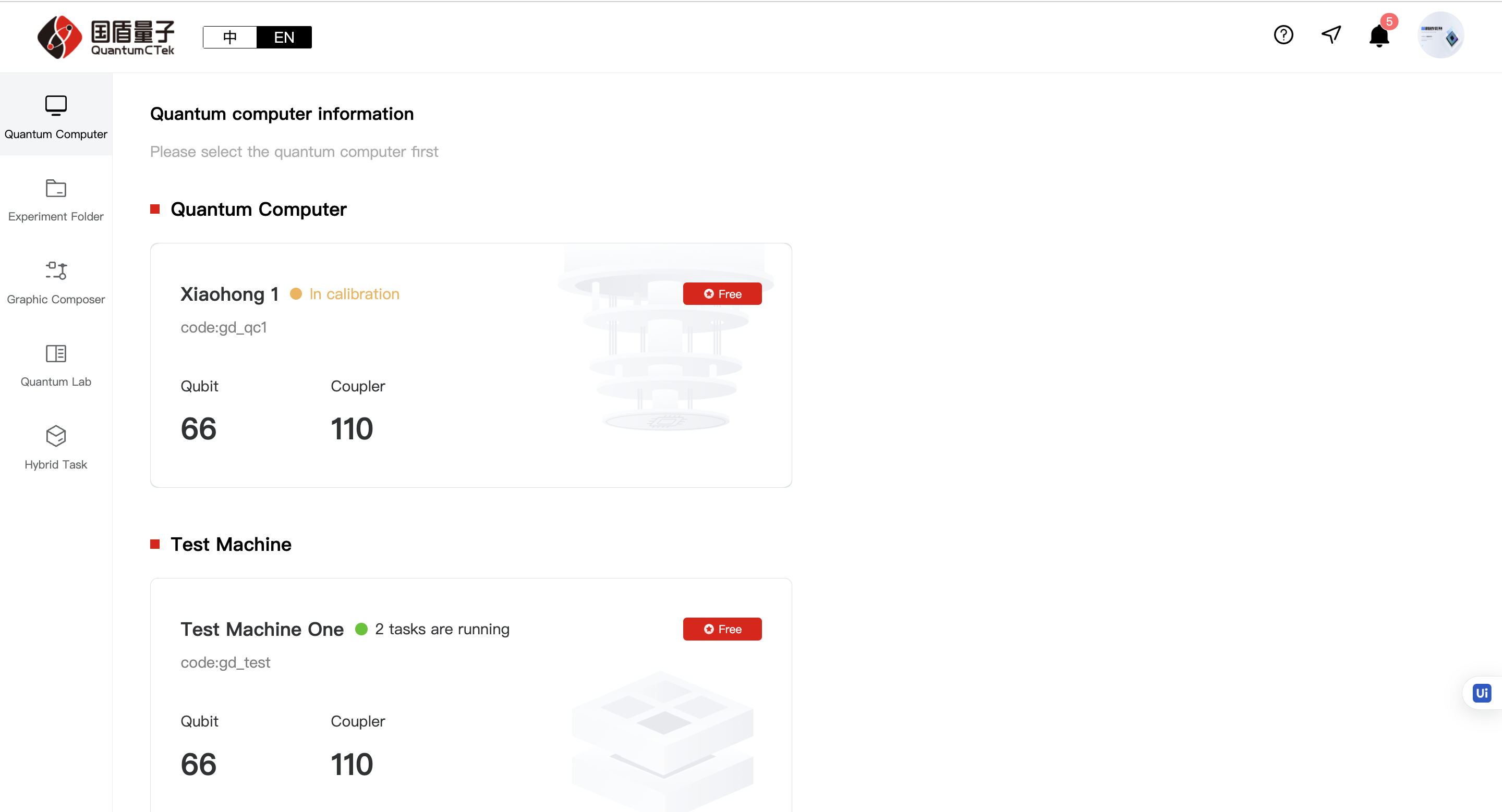
1)This page displays all quantum computers in different series, with basic information shown on the cards.
5.1.2 Enter the Graphical Laboratory Page
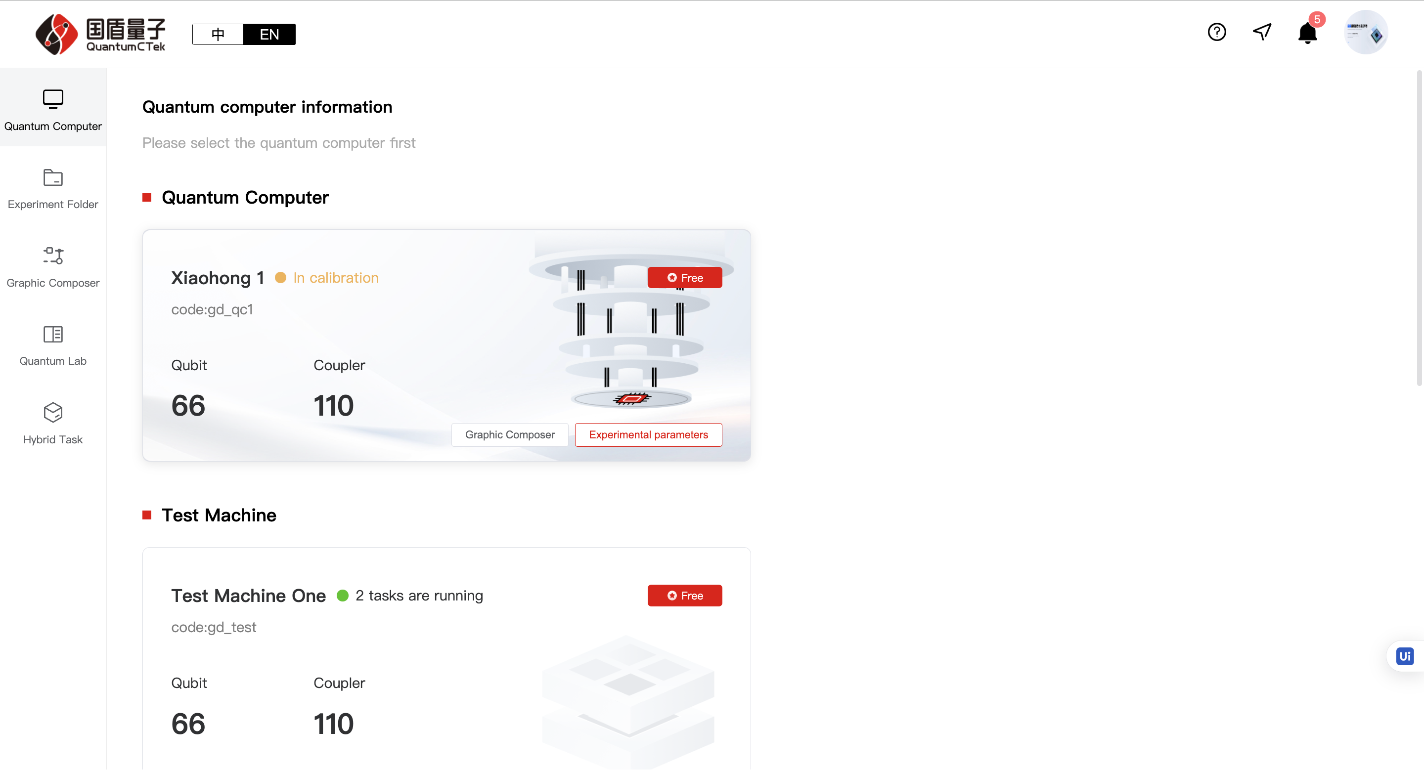
Select the quantum computer you need to use, hover over the card to enter the "Graphical Laboratory";

5.1.3 Enter the Experiment Parameters Page
Select the quantum computer you need to use, hover over the card to enter "Experiment Parameters";
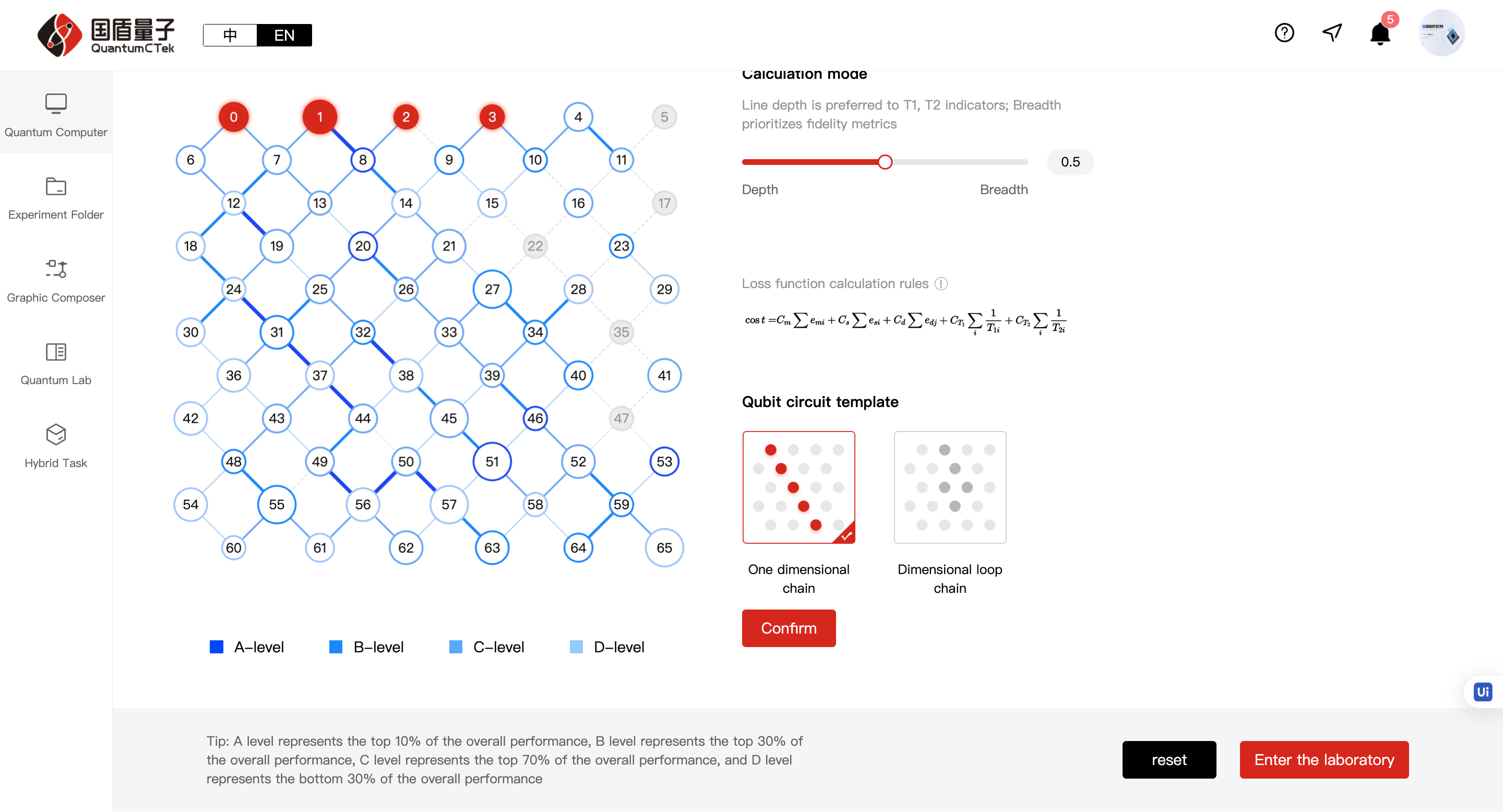
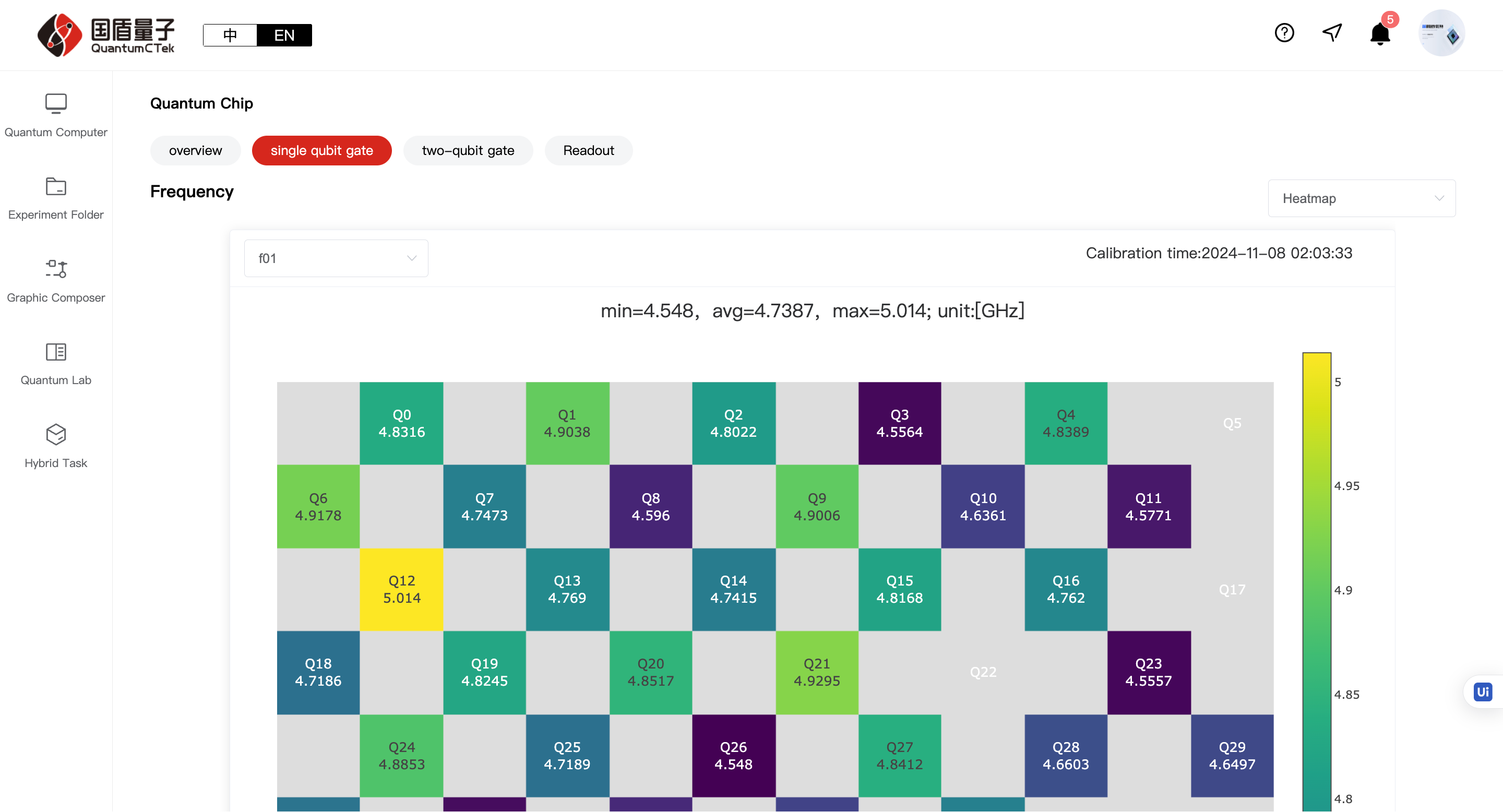
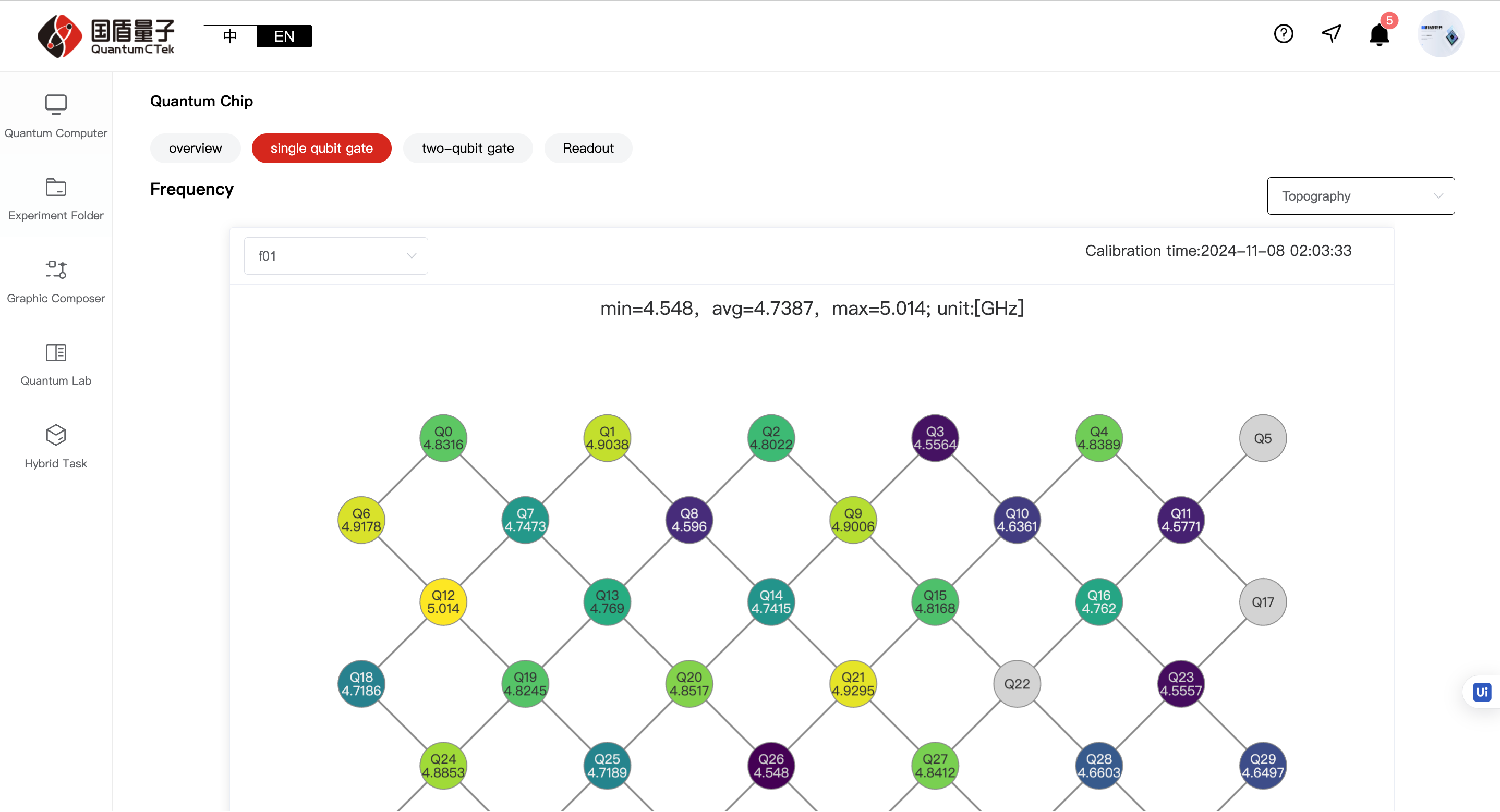
5.1.4 Experiment Parameters Page
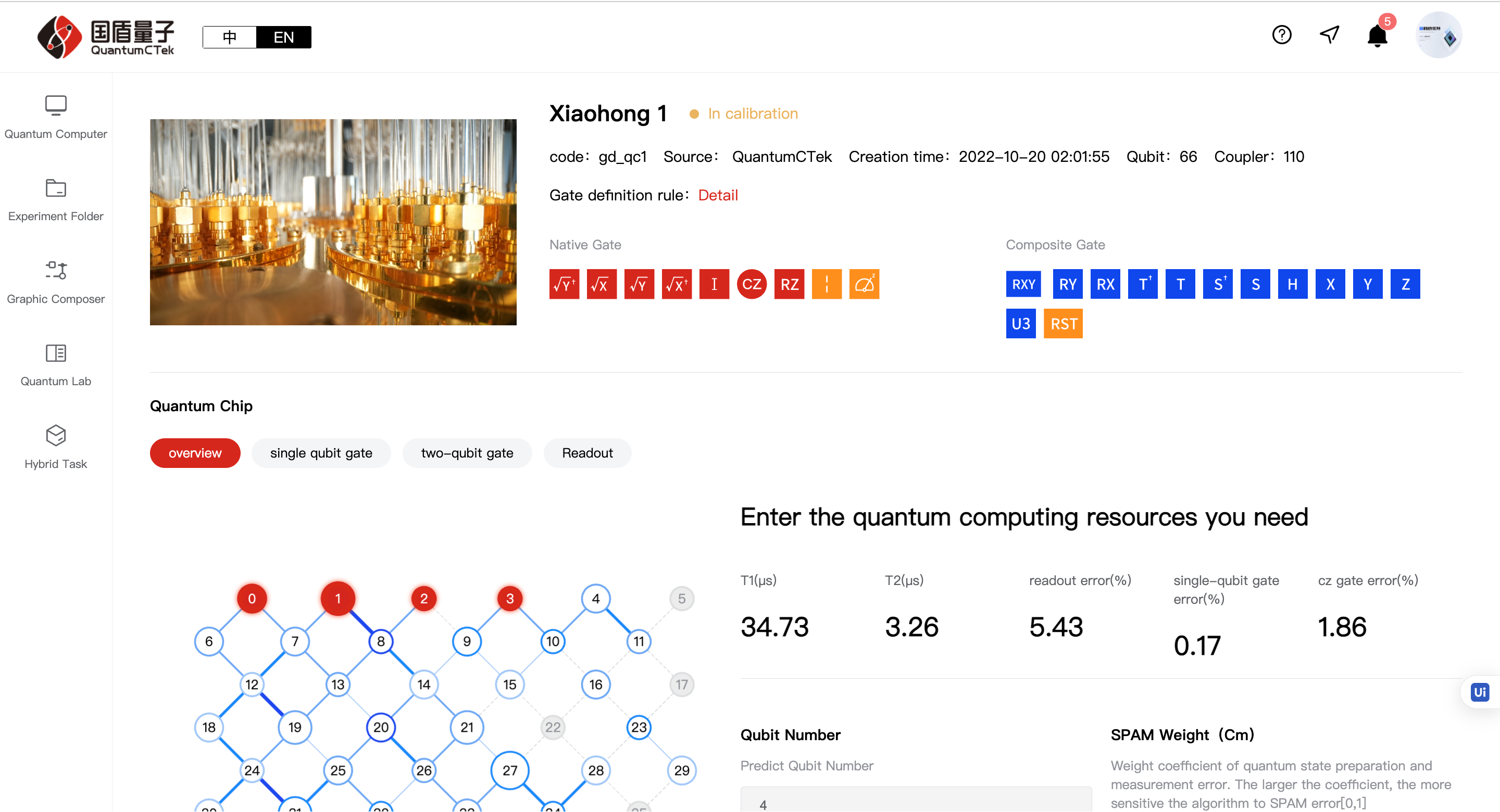
1)Details - Shows detailed information about the quantum computer.
2)Overview Page.
1 2 3 | |
3)Single-qubit gates, two-qubit gates, readout - displays corresponding QPU parameter values.
5.2 Experiment Collections
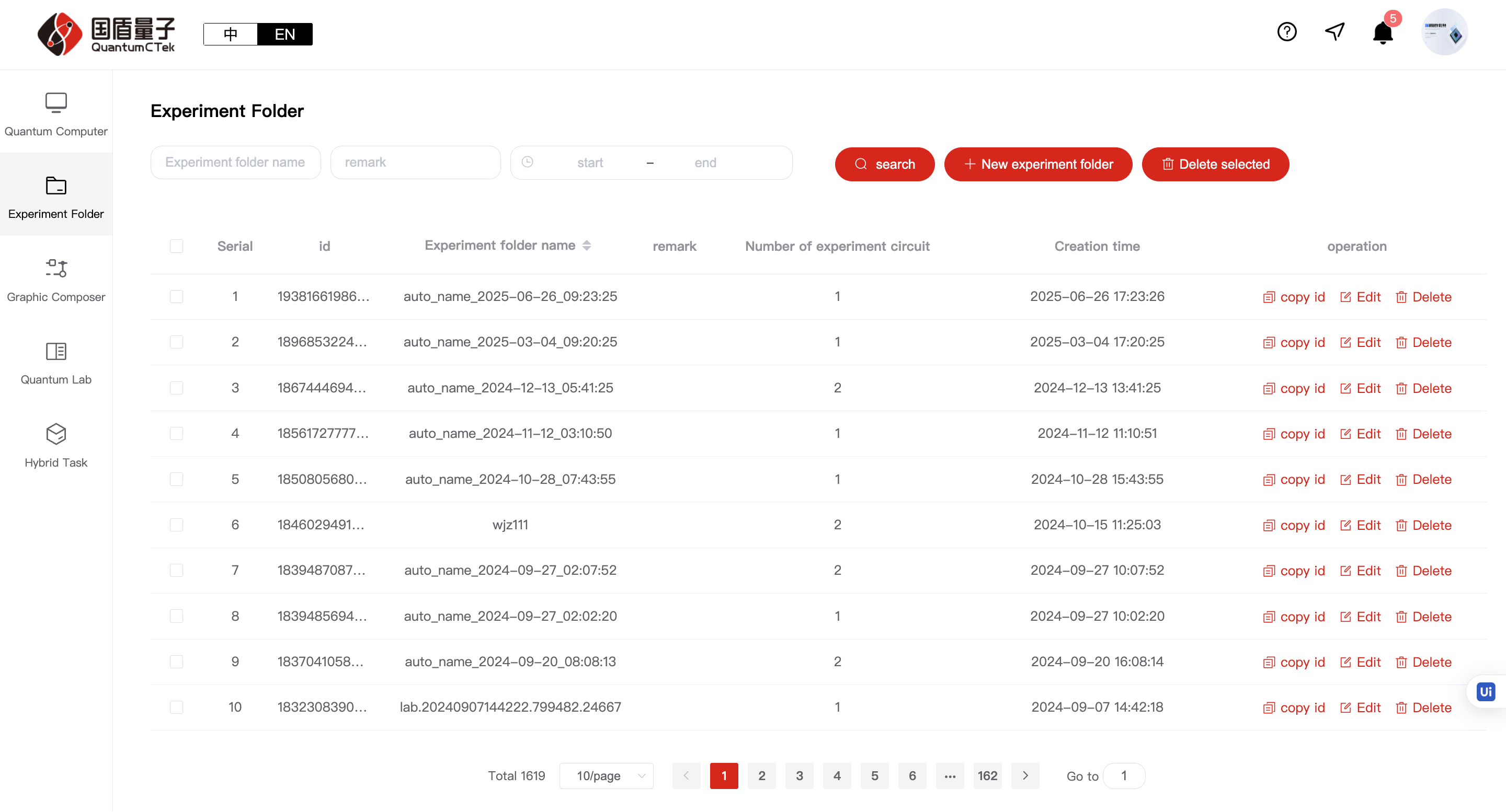
5.2.1 Experiment Collections Page
1) Can search, create, edit, delete experiment collections, copy ID
2)Click on a collection row to enter "My Experiment Circuits" page
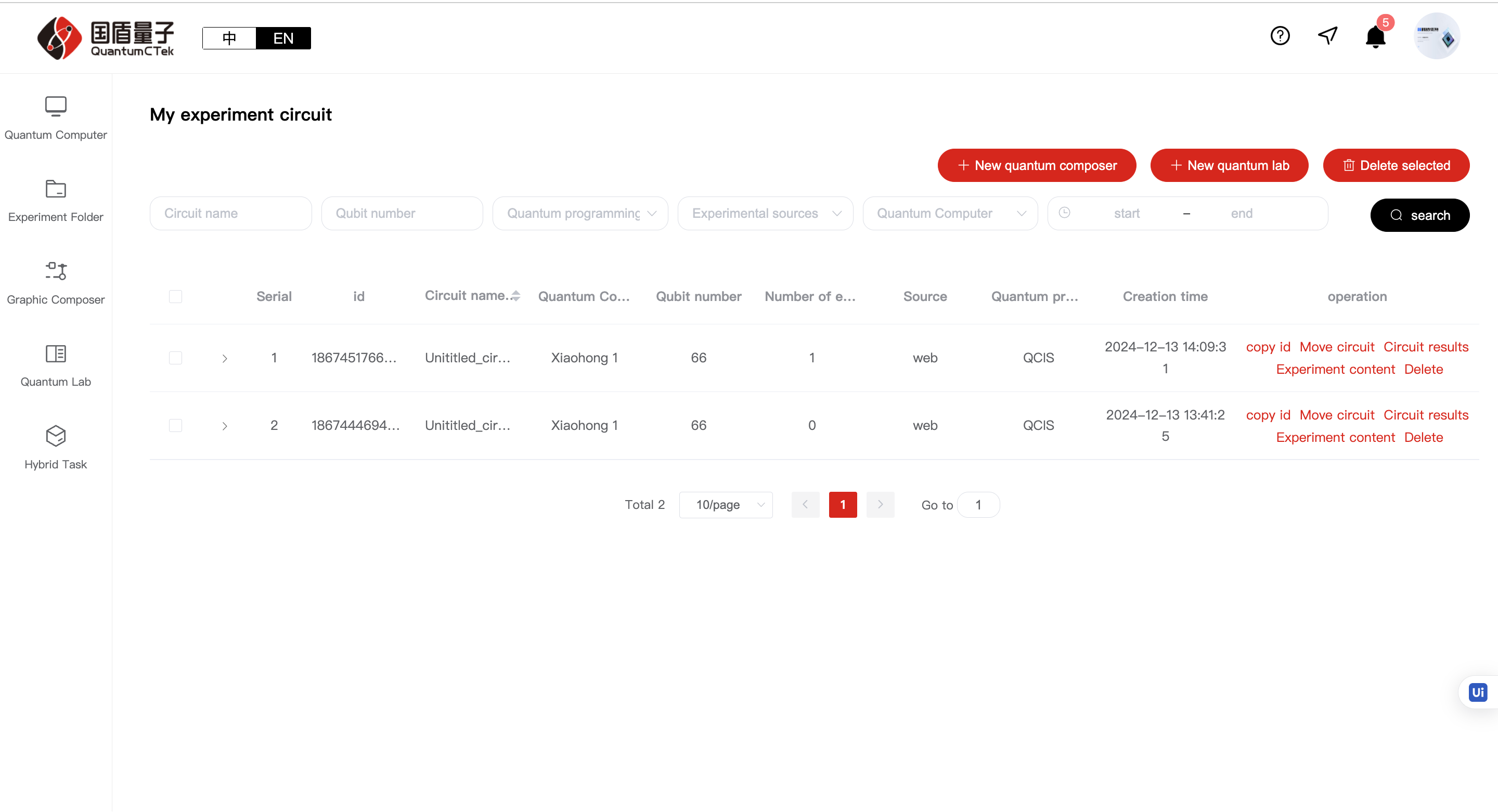
5.2.2 My Experiment Circuits Page
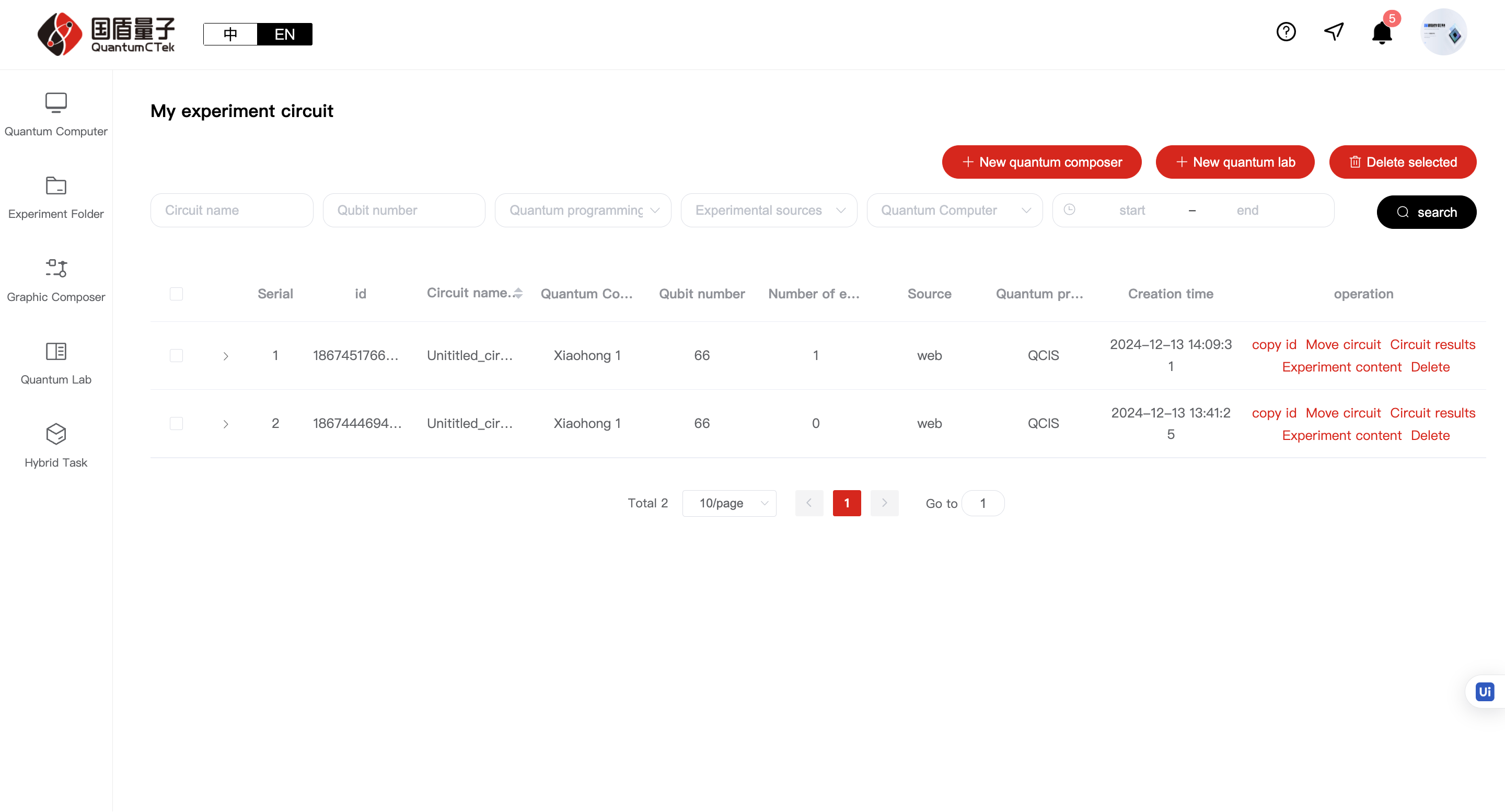
1)A series of operations can be performed on each circuit from the right side
2)Each circuit can be expanded to view execution results
5.3 Graphical Laboratory
There are three ways to enter the graphical laboratory:
1) As above, Quantum Computer page - Graphical Laboratory
2) Quantum Circuit page - Create New Graphical Experiment
3) Direct click on Graphical Laboratory
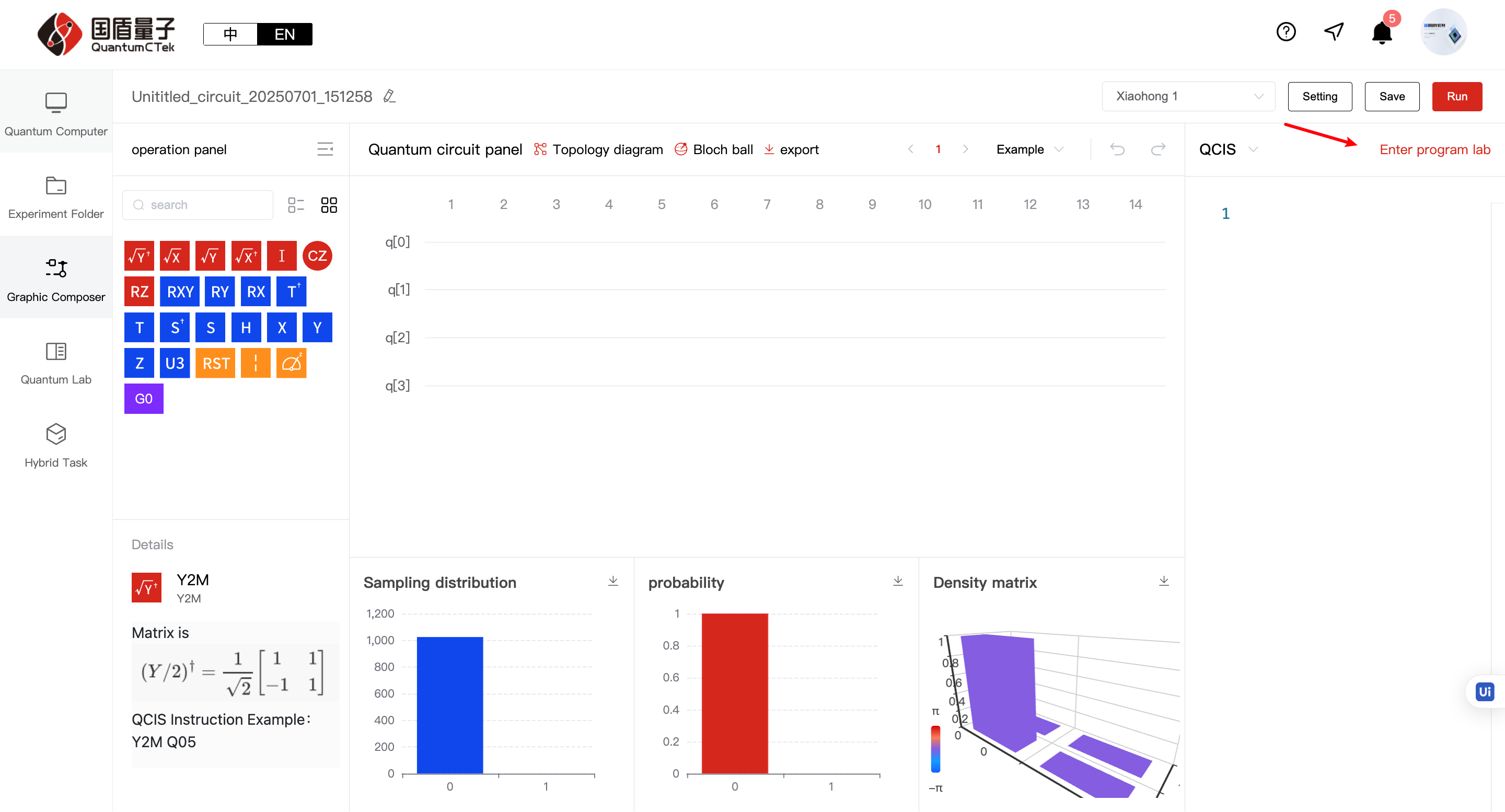
5.3.1 Understanding the Graphical Laboratory;
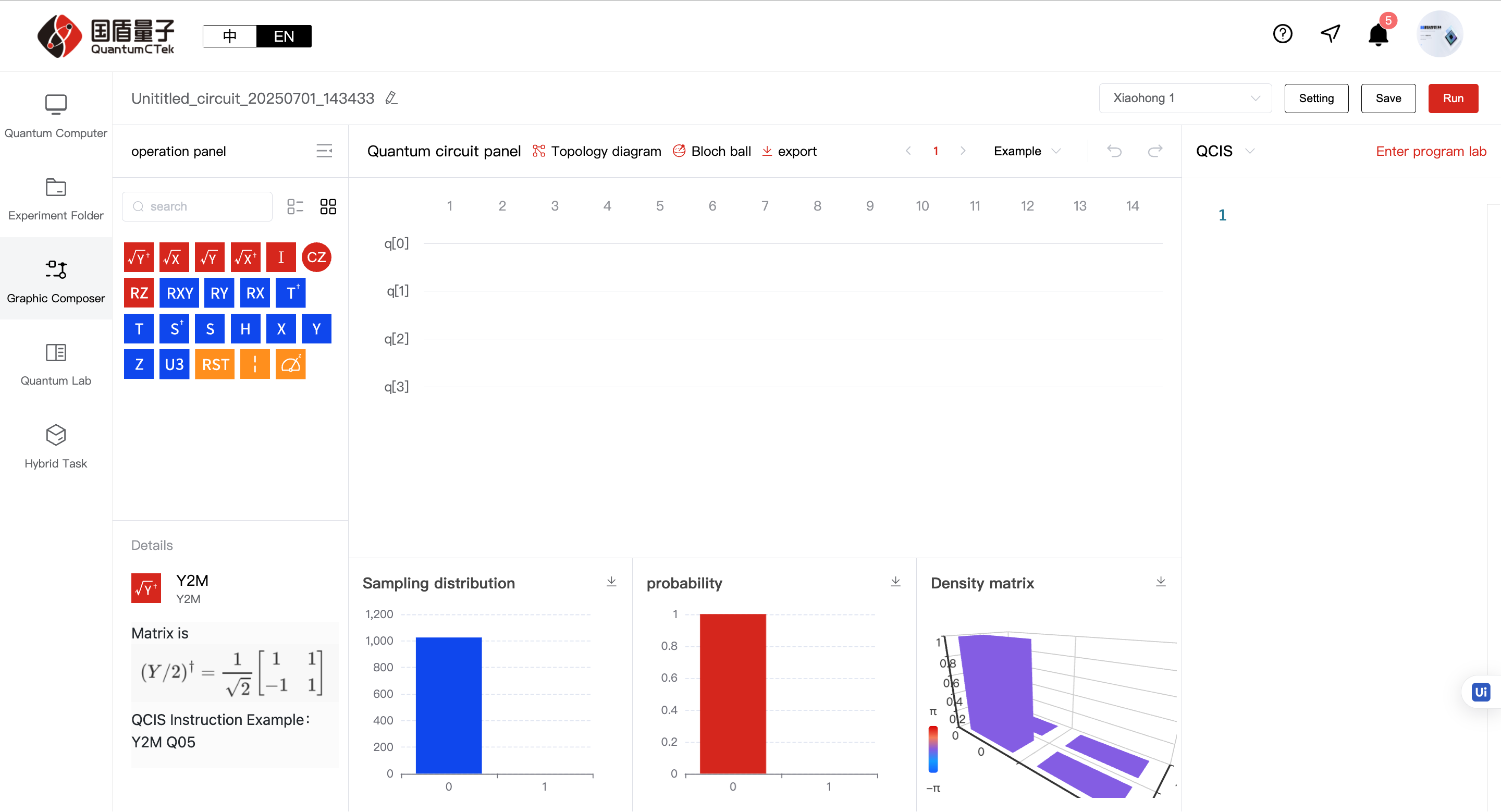
The overall graphical laboratory can be divided into four areas: Title area at the top, Left content (Qubit gate area), Middle content area (Quantum circuit area), Right content area (QCIS instruction programming area)
1) Top Title Area
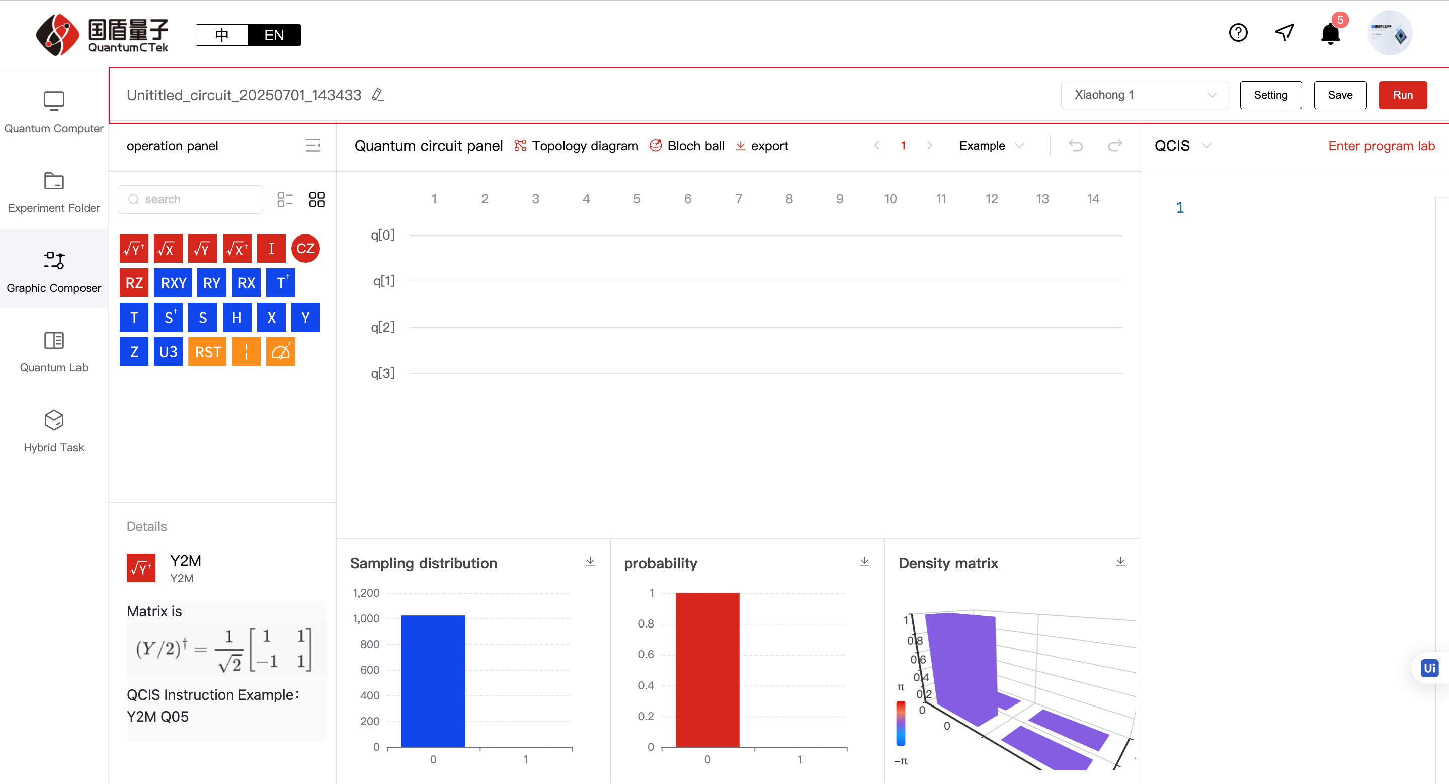
a. Experiment name on far left: Can be modified
b. Four modules on the right:
1 2 3 | |
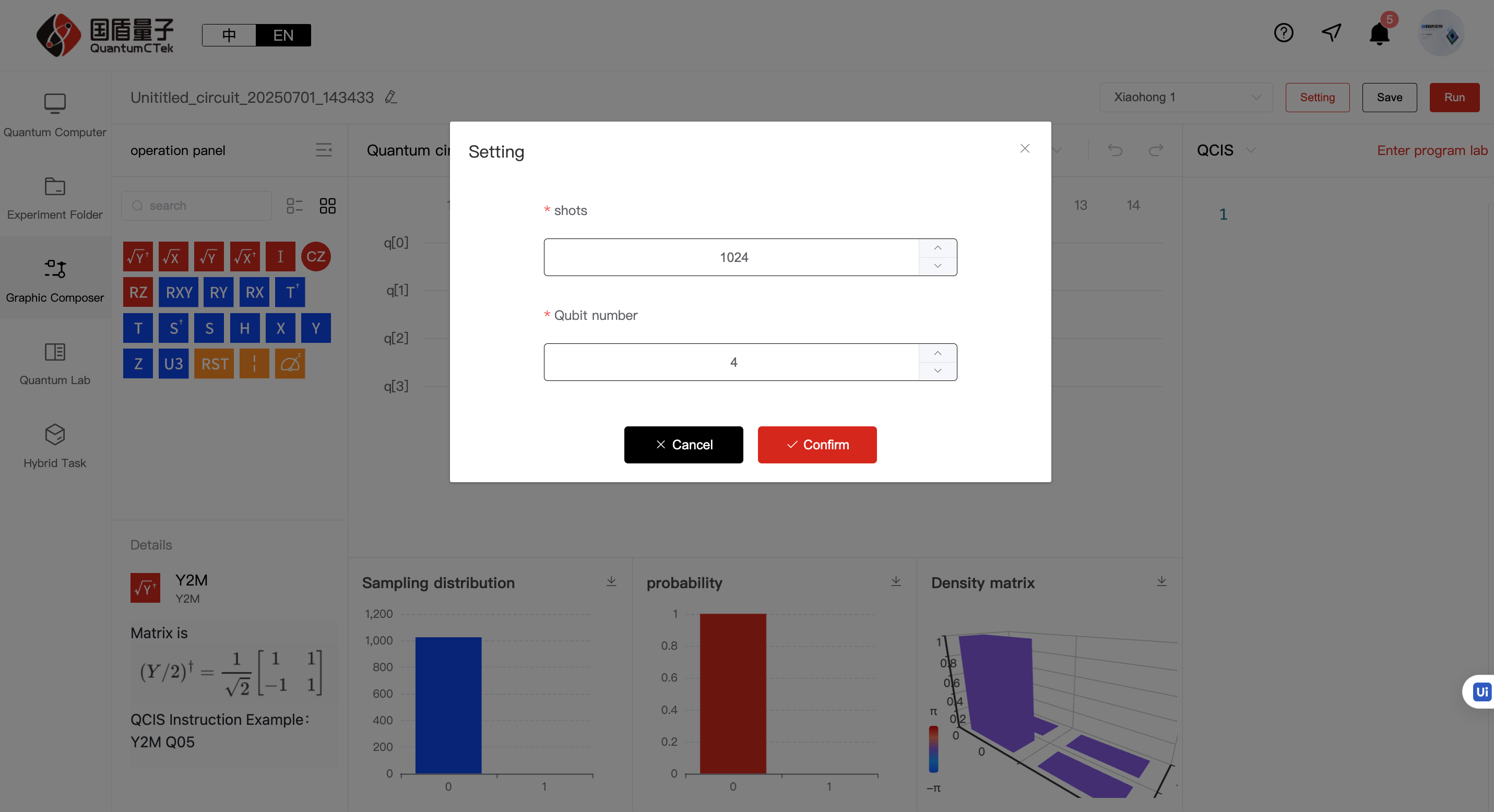
1 2 3 | |
2) Left Content (Qubit Gate Area)
All operable logic gates and measurement gates, including single-qubit gates for basic logic operations (Z, Y, Z, Rx, Ry, Rz, Rxy, S, SD, T, TD, RST, X2P, X2M, Y2M, Y2P, H, i, B, U3, CNOT); two-qubit gates (CZ, ISWAP, SWAP); three-qubit gates (CCX, CCZ), custom gates and measurement gates (M), where custom gates are combinations of several gates. Quantum gates can be understood as musical notes - you need to understand their meaning to perform calculations. For more about qubit gates and mathematical operations, see the QCIS User Manual: https://quantumctek-cloud.com/documentDetail/1610850004853854210.html
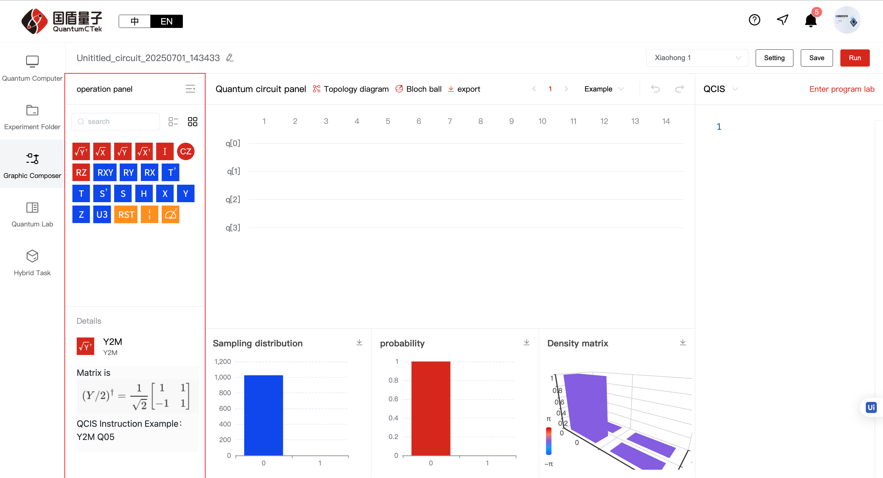
a. Right panel button: Can collapse panel
b. Search input box: Can search gate names
c. Two buttons right of search: Button 1: Show gates by category, Button 2: Show all gates mixed
d. Text area below: Shows gate icons, names and details
3) Middle Content Area (Quantum Circuit Area):
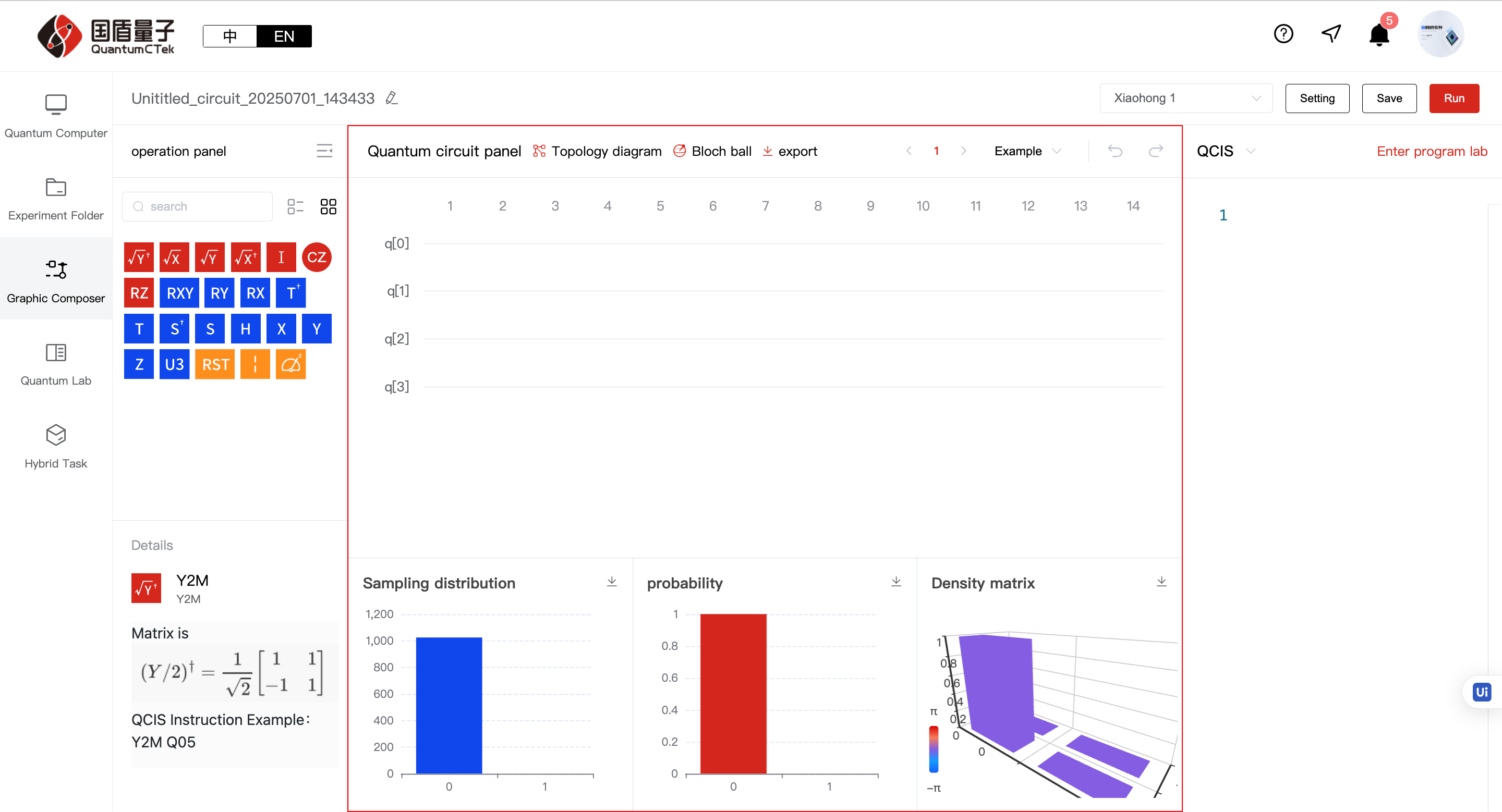
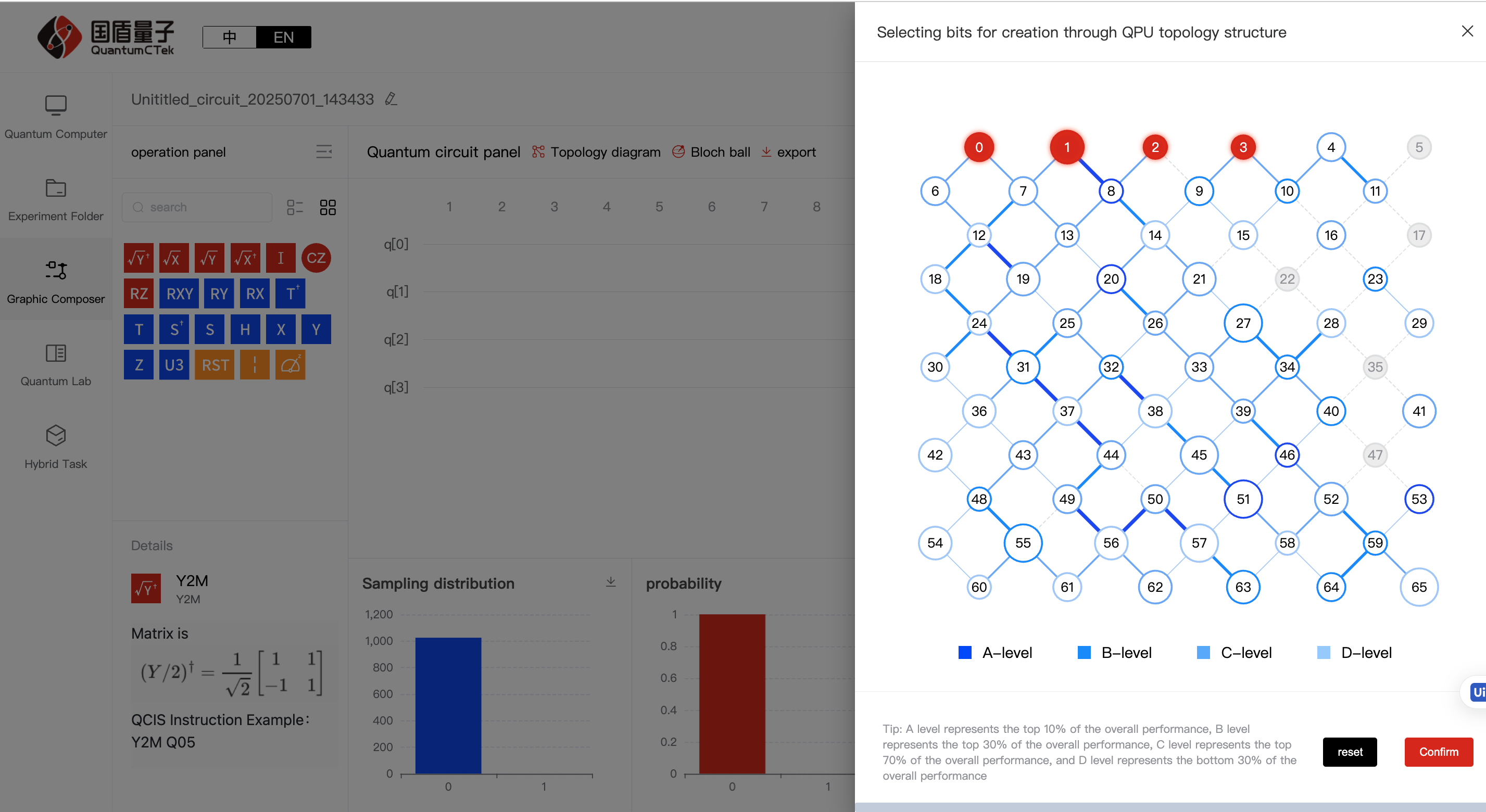
a. Topology diagram: Click to show topology, can select qubits and view qubit performance info
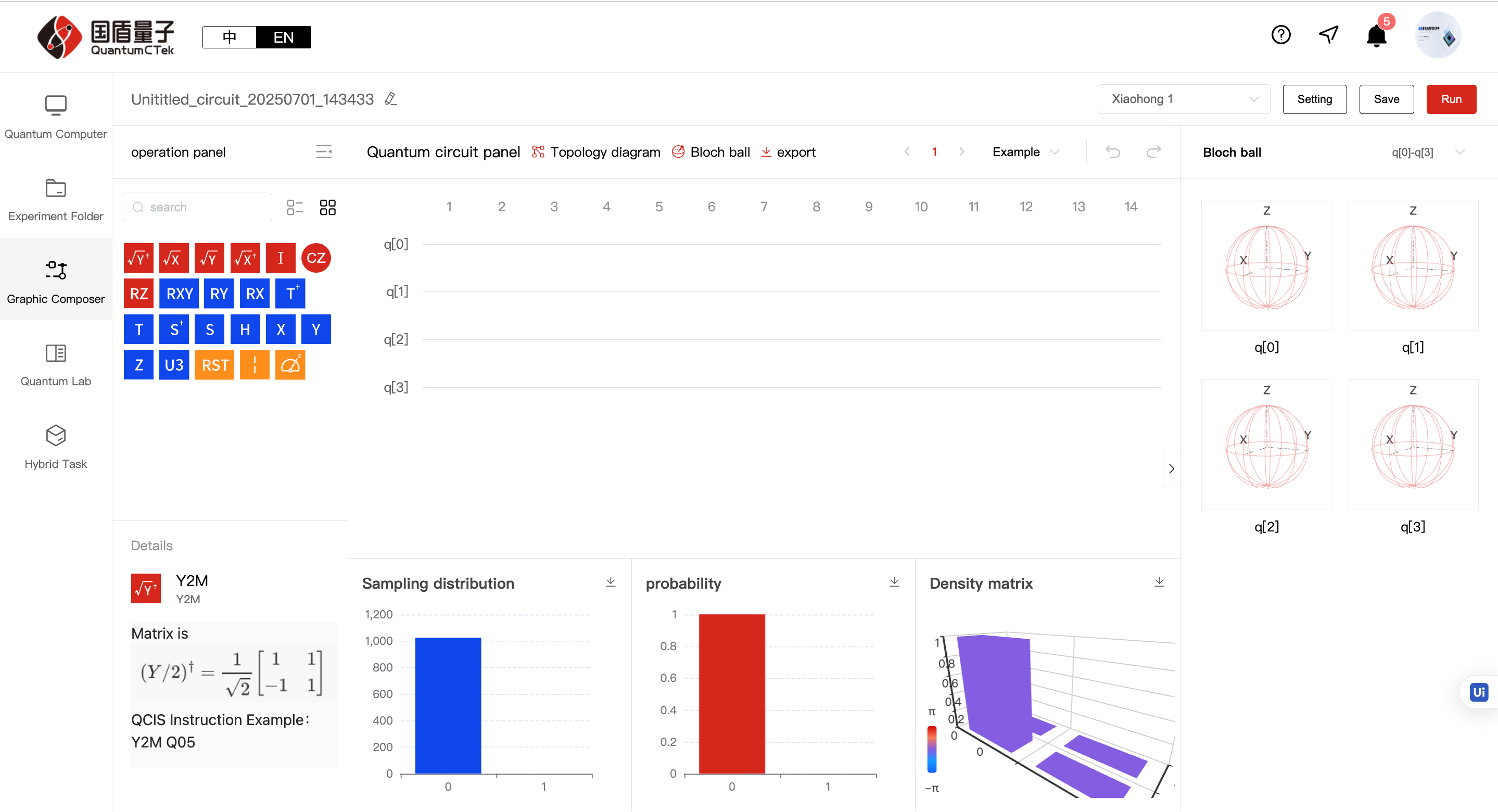
b. Bloch sphere: Click to show Bloch sphere, can view qubit state changes
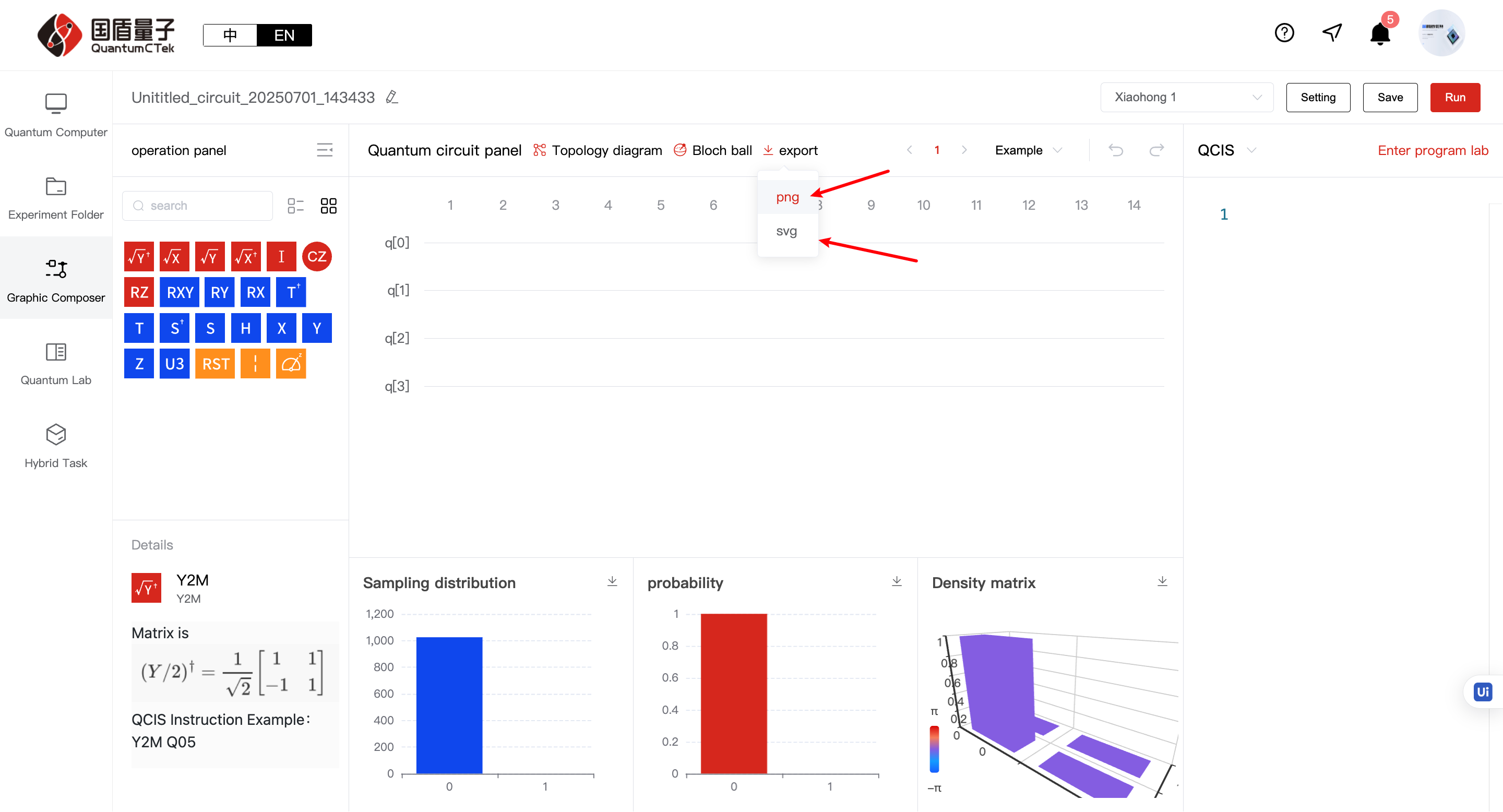
c. Export: Can choose png and svg
d. Pagination: Shows quantum circuit in pages of 30 columns
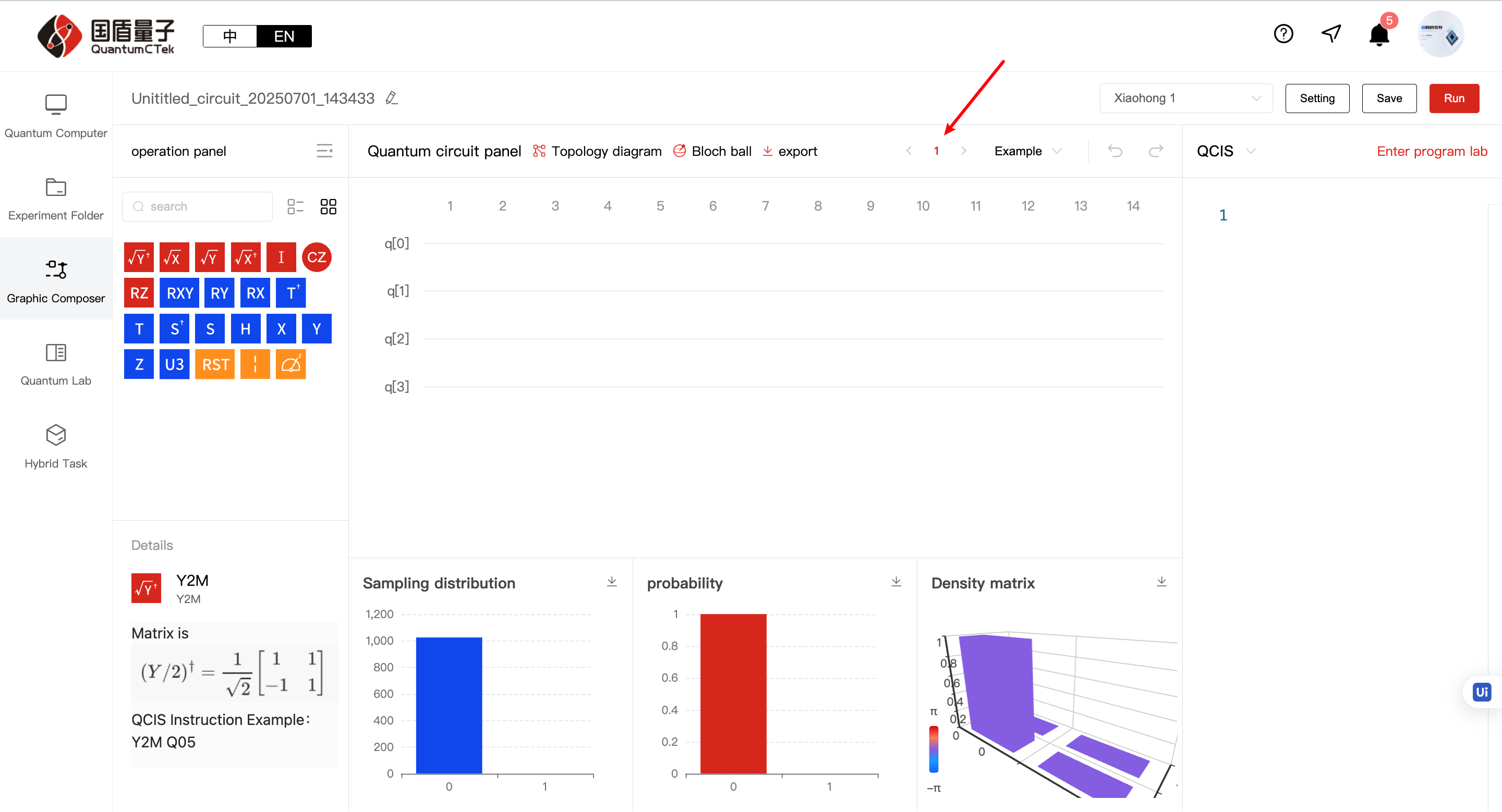
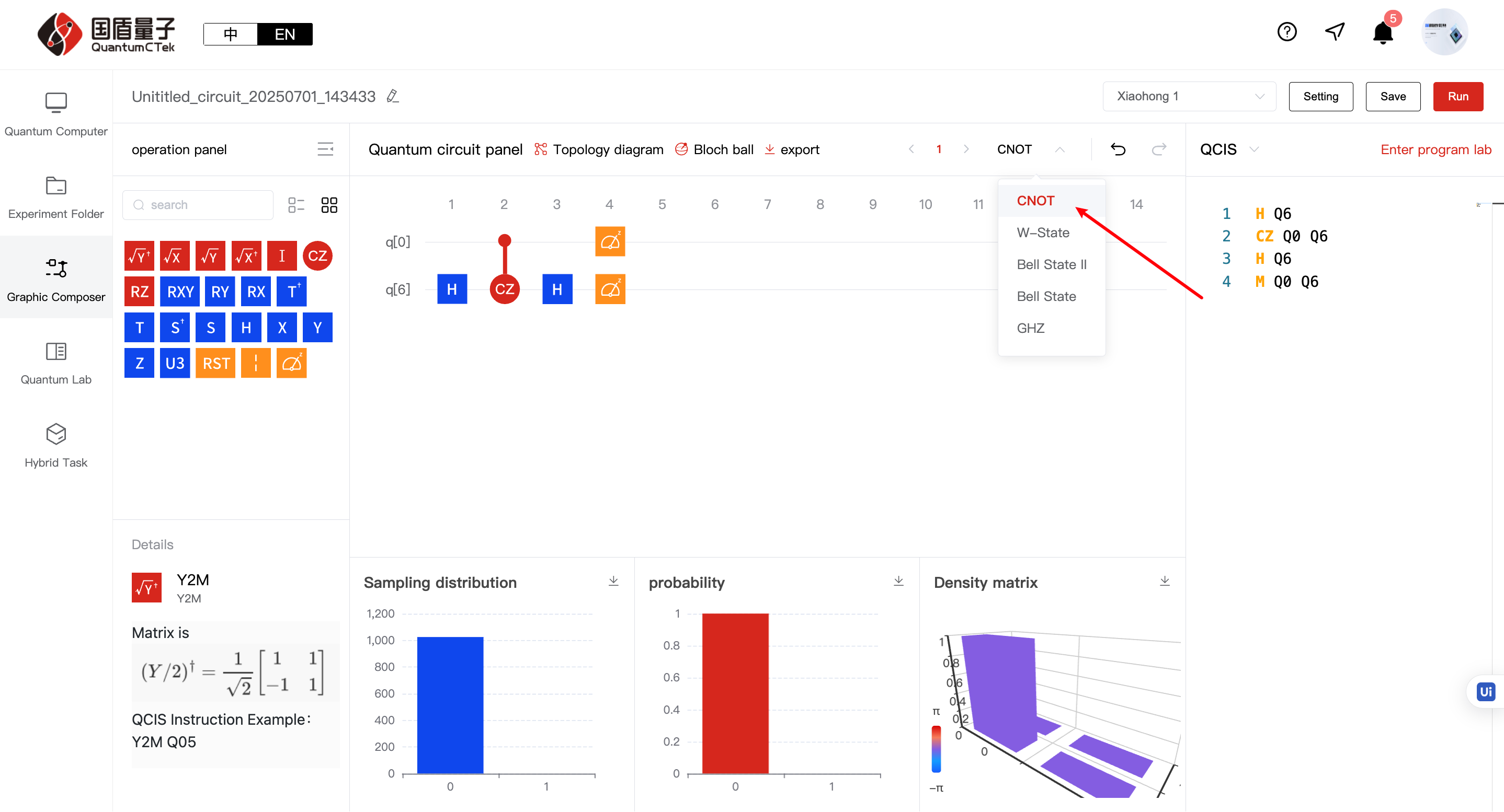
e. Example code: Can select pre-written QCIS instruction sets to import into programming box
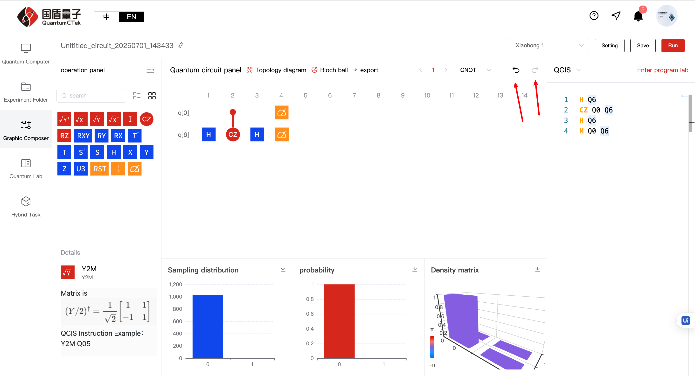
f. Undo/Redo: Can undo, redo quantum circuit operations
g. Quantum Circuit Graphics Area:
-
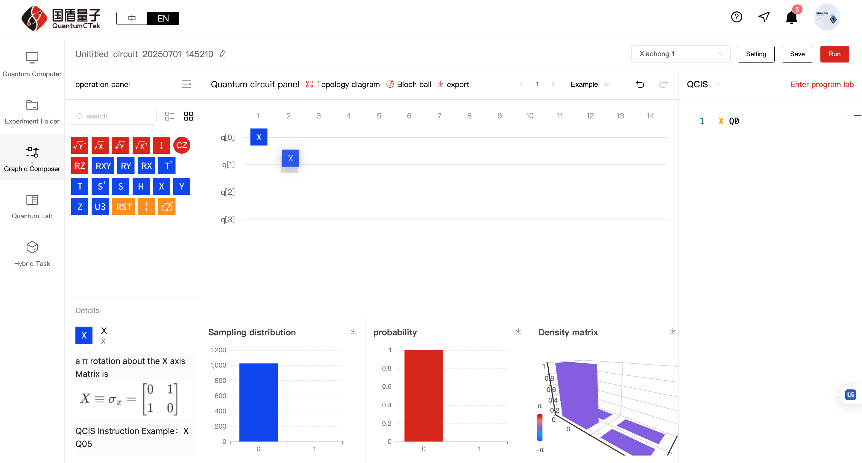
Drag quantum gates into the circuit graphics area to write quantum circuits. This area can be understood like a musical staff. Placing correct quantum gates (notes) on the graphic circuit (staff) completes a beautiful piece! QCIS instructions are simultaneously generated in the programming box
-
Can drag and drop in this area - dragging outside the circuit panel deletes gates, dropping on quantum circuit panel generates gates
-
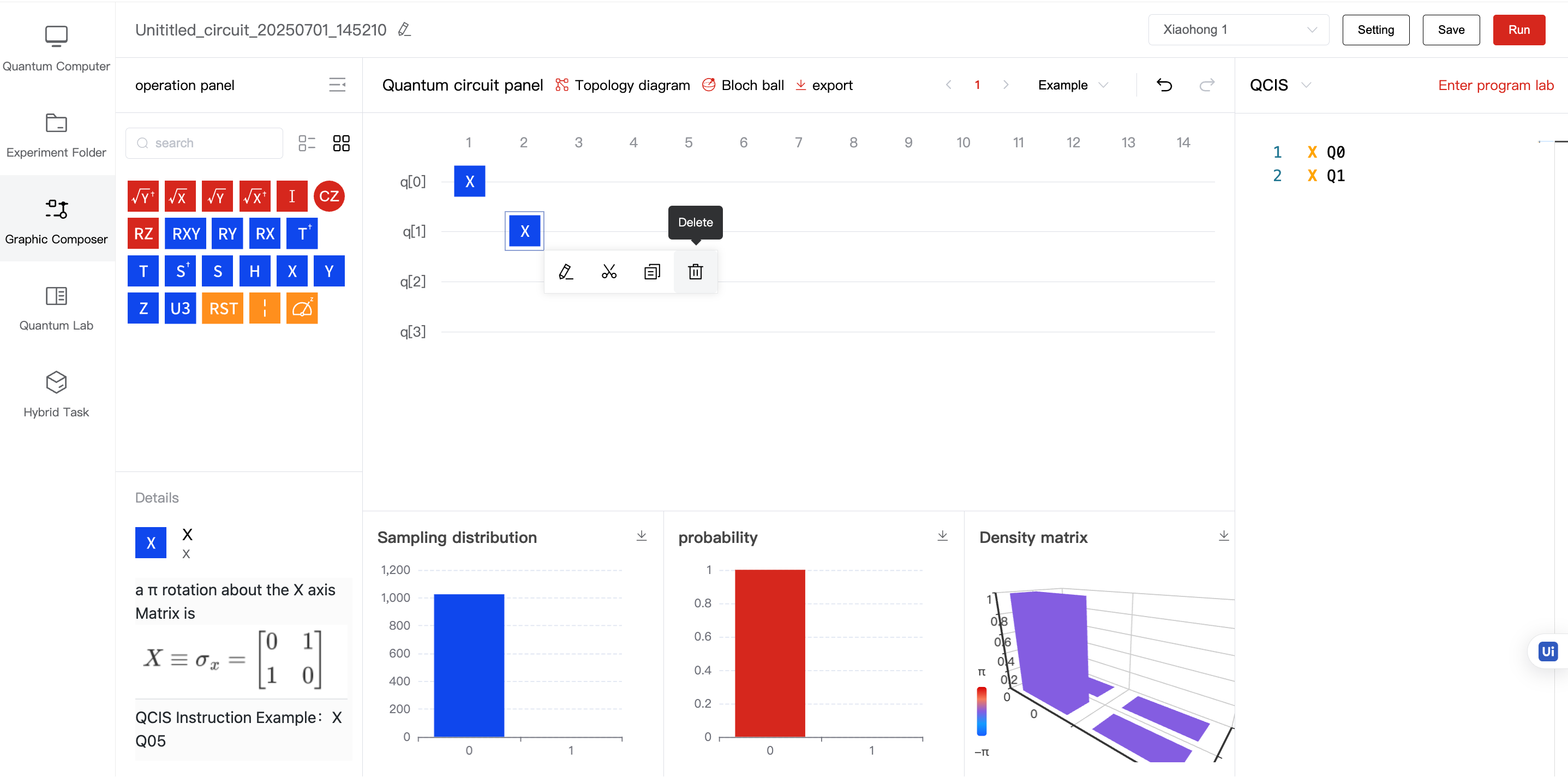
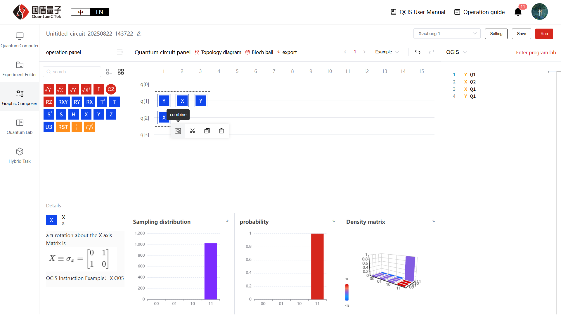
Right-click menu: Divided into single gate and multi-gate operations, single gate (right click), multiple gates (left click select then right click)
3.1 Edit (single gate only), Cut (single/multiple), Copy (single/multiple), Paste (single/multiple) Delete (single/multiple,You can click the button or use the Backspace key to operate it)
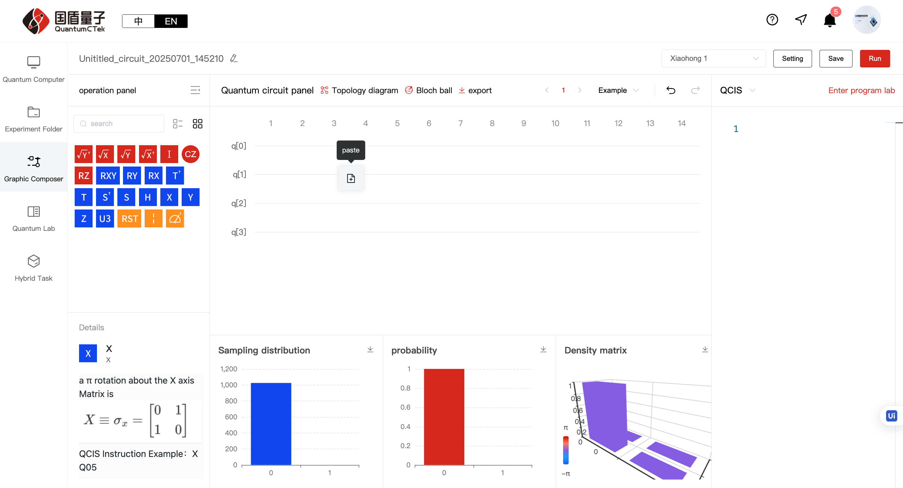
Cut and Copy: After these operations, pasting becomes available
Paste: After cut or copy, select suitable position, right click to paste, quantum gate will be generated at that position
Delete: Can remove quantum gates
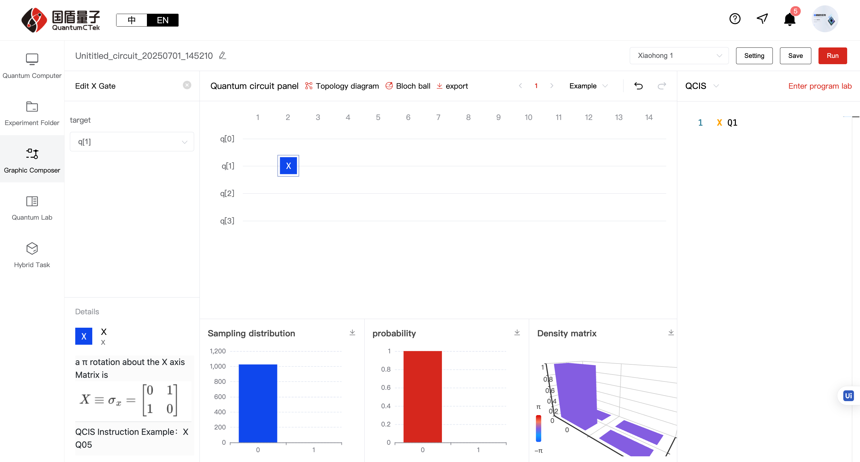
Edit: Can adjust target gate's qubit, works for both single and two-qubit gates
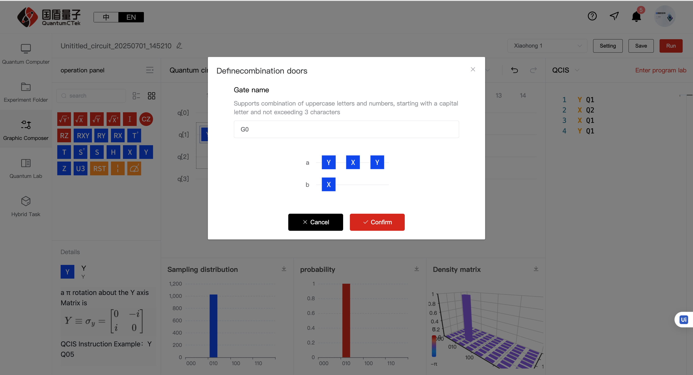
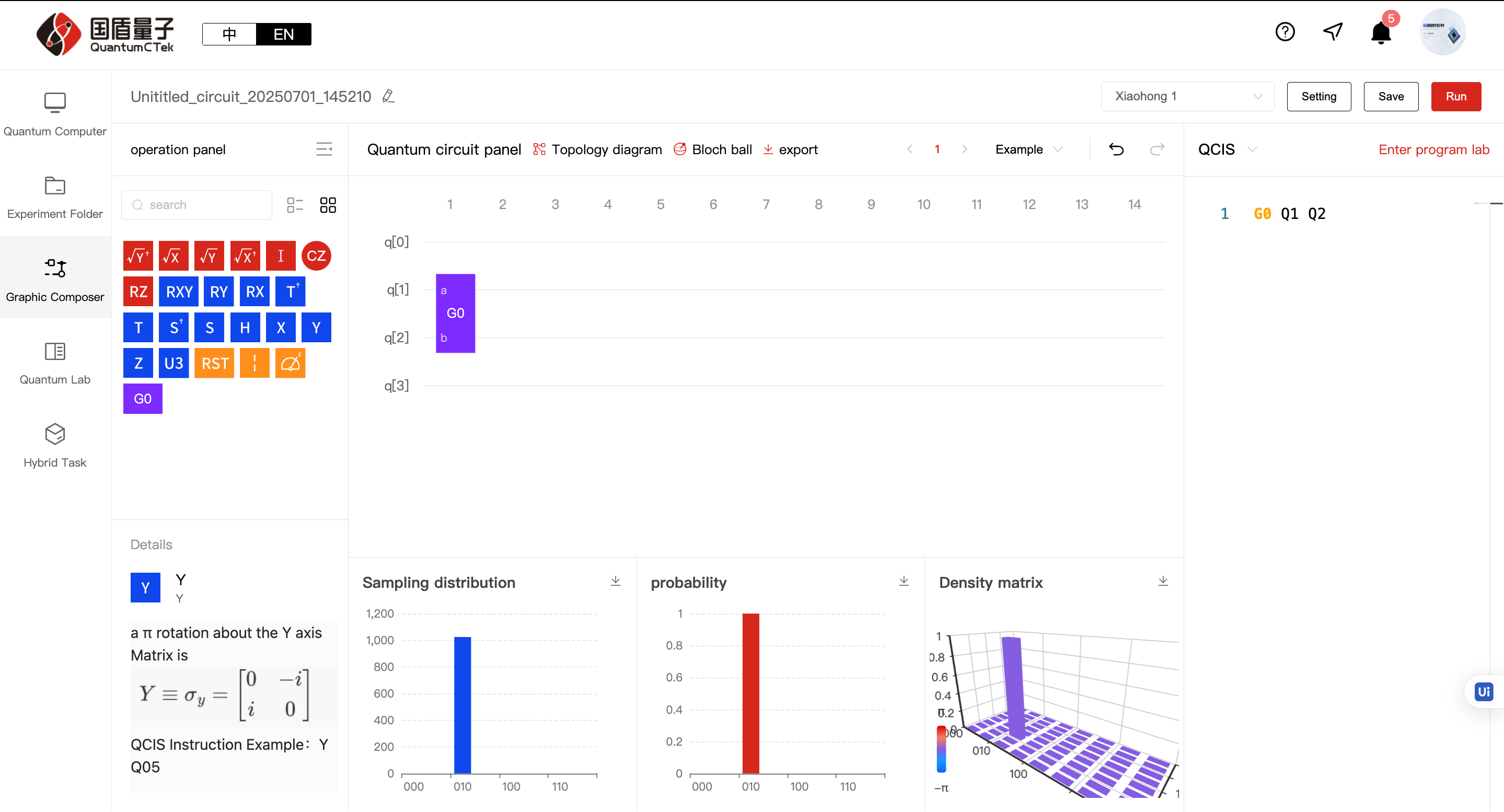
3.2 Combine (multiple only): Except for custom gates and measurement gates, other gates can be combined when multiple selected. After clicking combine and entering a name, a custom gate (purple) appears in the gate area and can be dragged/dropped normally.
3.3 Split (for combined gates, single/multiple): Can split back into multiple pre-combined gates.
Before splitting:
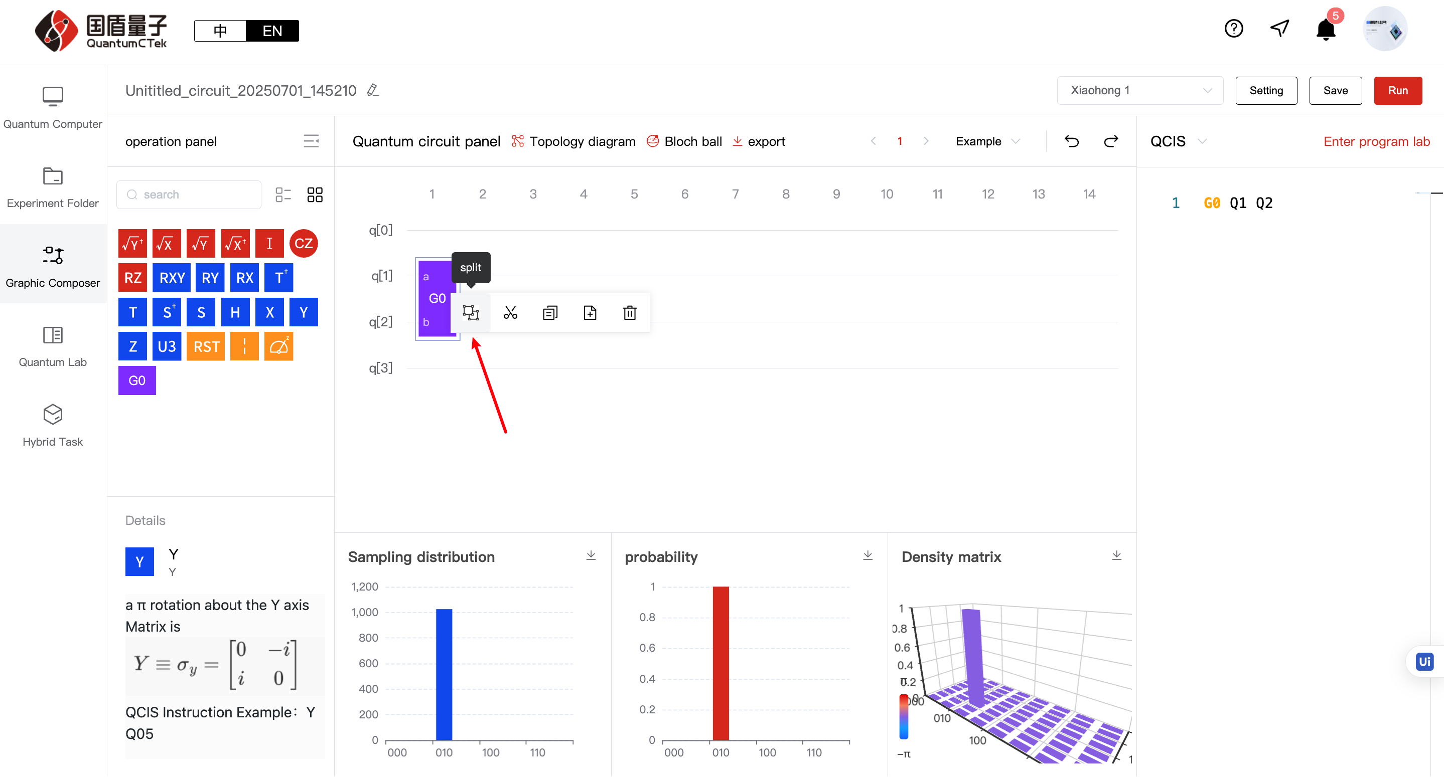
After splitting:
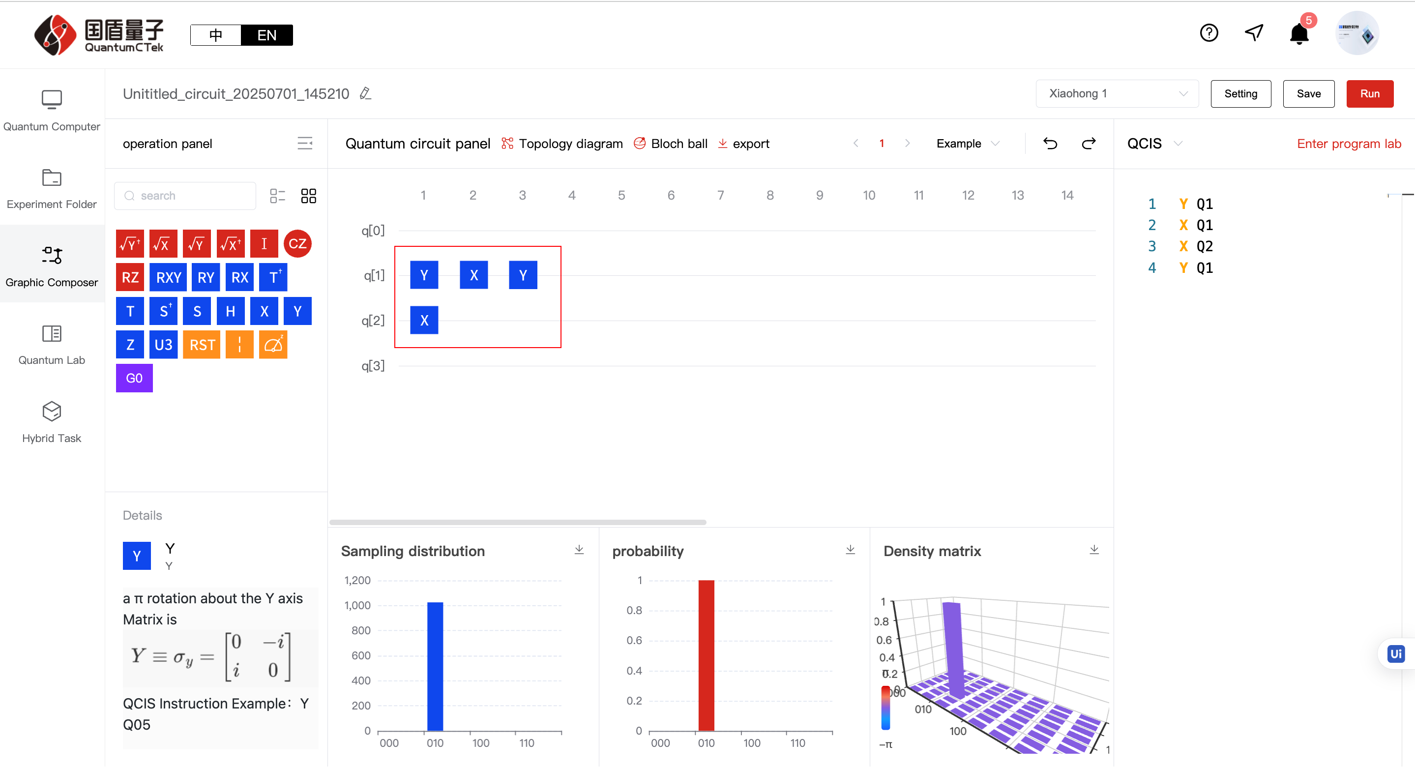
h. Bottom histogram area: When quantum circuit changes, updates sampling distribution, probability, and density matrix data in real time
4) Right Content Area (QCIS Instruction Programming Area)
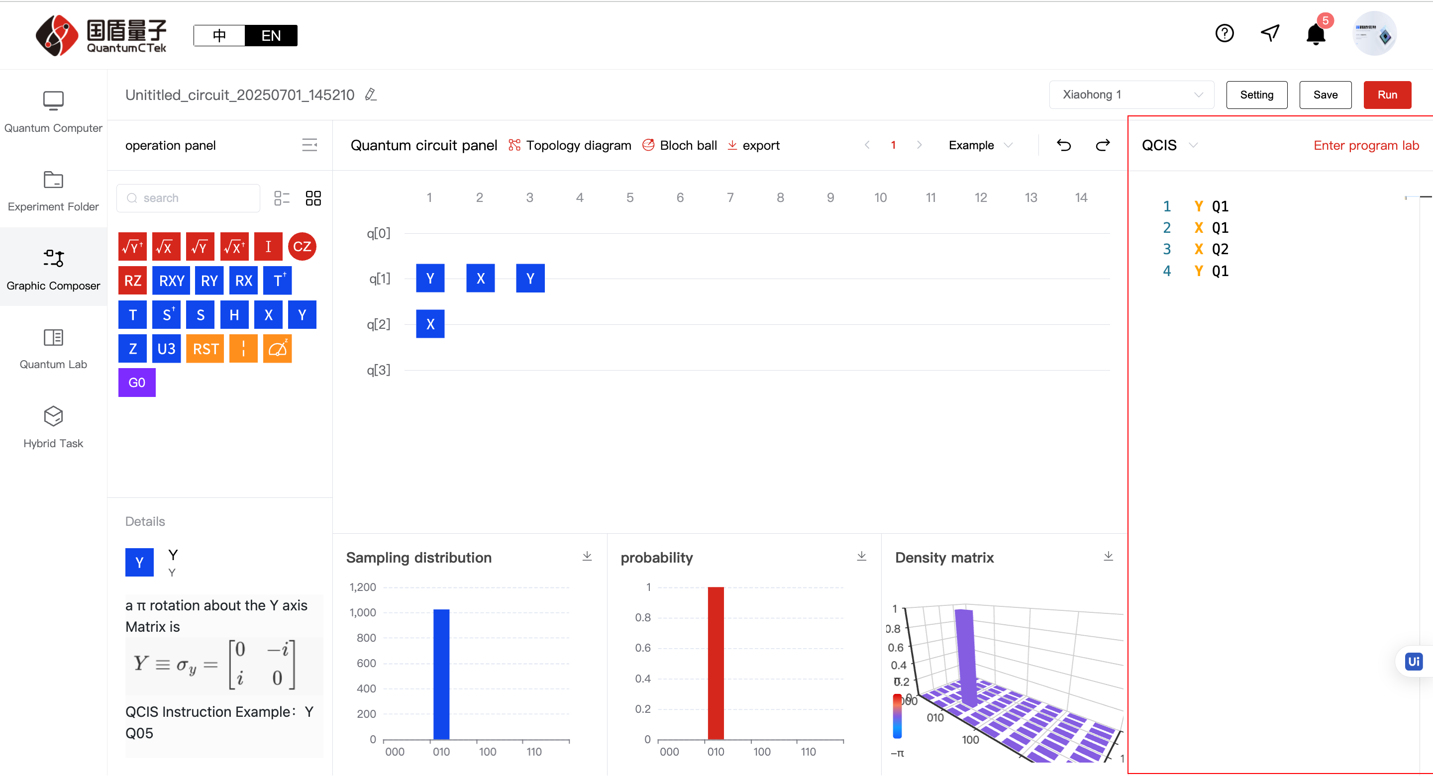
a. Programming area: Choose programming language in top left, write QCIS instructions below. Real-time validation of QCIS syntax and run conditions, shows errors if conditions not met, updates quantum circuit when correct
b. Enter Programming Lab: Click to jump to programming laboratory
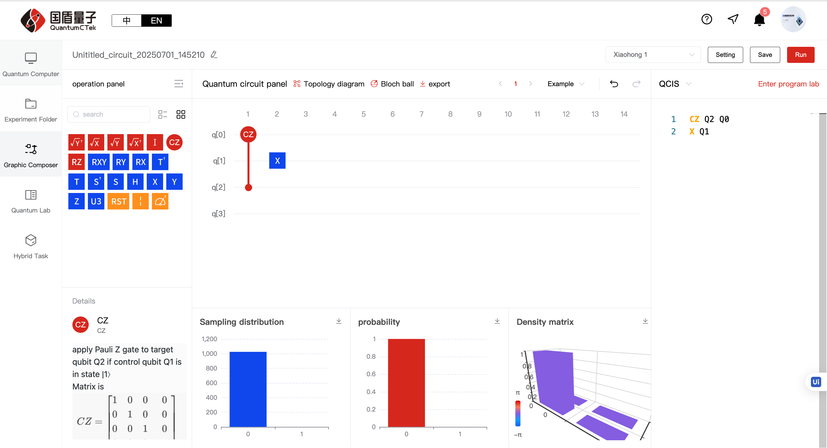
5.3.2 A Complete Quantum Circuit;
1) A complete (but not necessarily useful) quantum circuit consists of at least two parts: logic gates and measurement gates
Logic gates include single-qubit gates (red) and two-qubit gates (blue), there is only one type of measurement gate
2) After completing circuit writing, click "Run" to conduct experiment. Returns to My Experiment Circuits page to await results.
5.3.3 Understanding Experiment Collections and Circuits;
Observant friends will notice experiments appear in a default collection after completion. What does this collection mean? Why do we need it?
First, an experiment collection is a place to store a series of experiment circuits, like a folder for storing files:
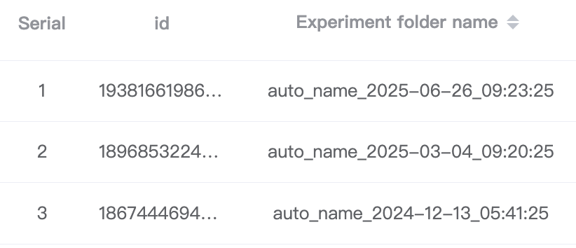
Why do we need this folder? Because many experiments and algorithms cannot be completed with just one circuit. QuantumCTek Computing Cloud Platform created this folder system to help experimenters use the laboratory in an organized and convenient way for their algorithm experiments
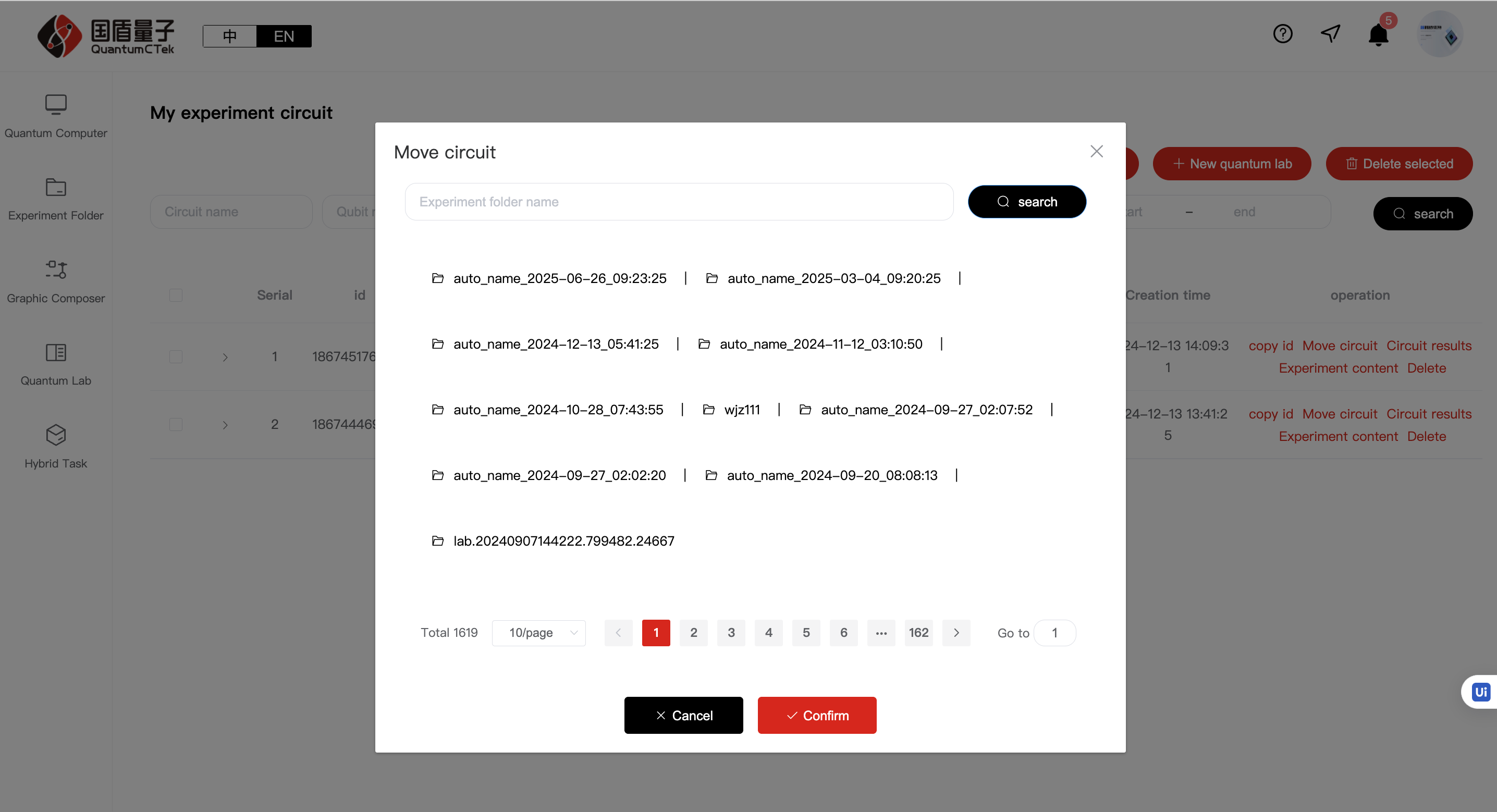
How to use these folders? There are two methods:
1. After completing a quantum circuit, it saves to the default folder. Click to enter that folder, find the needed circuit task, click "Move Circuit" to move it to the corresponding folder
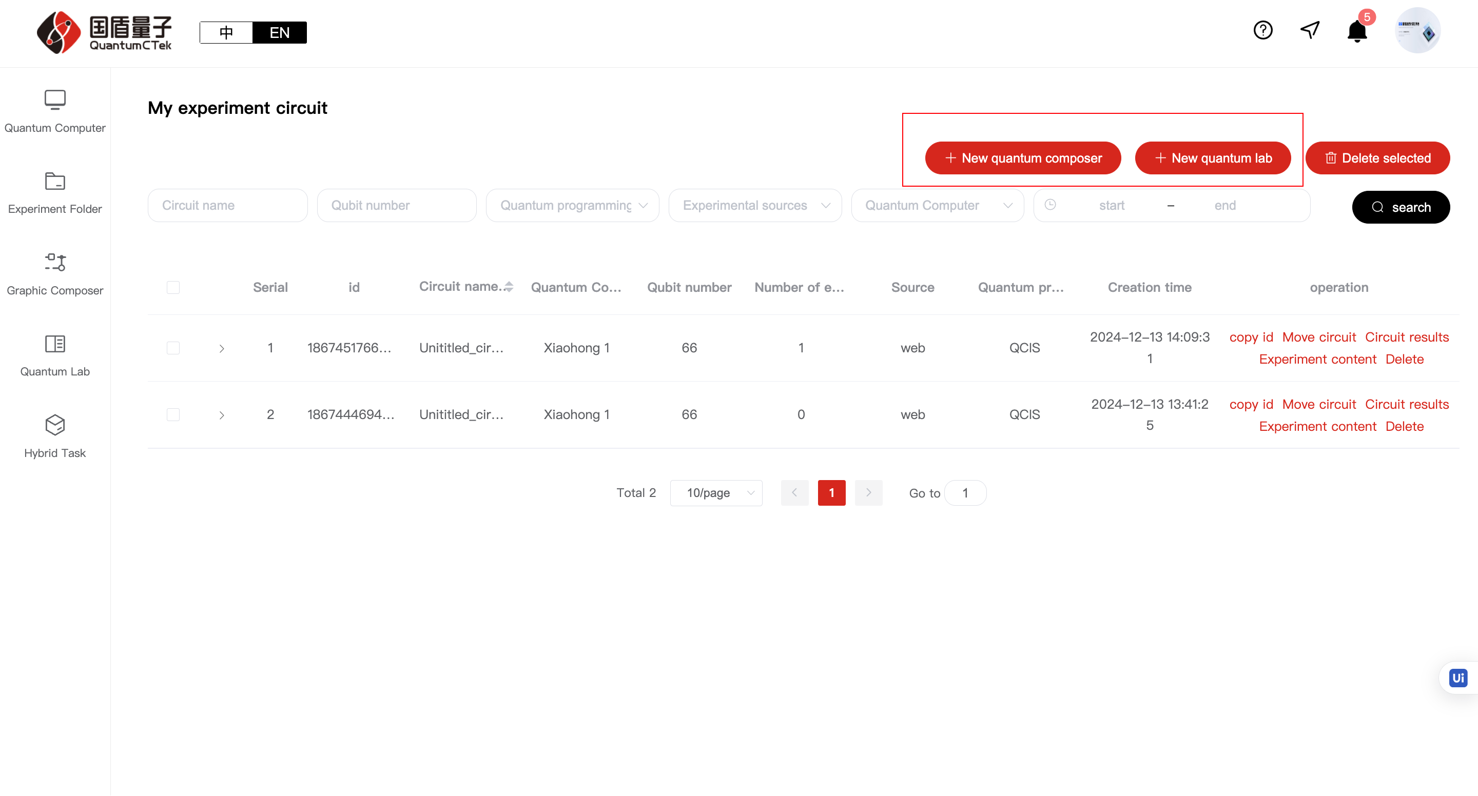
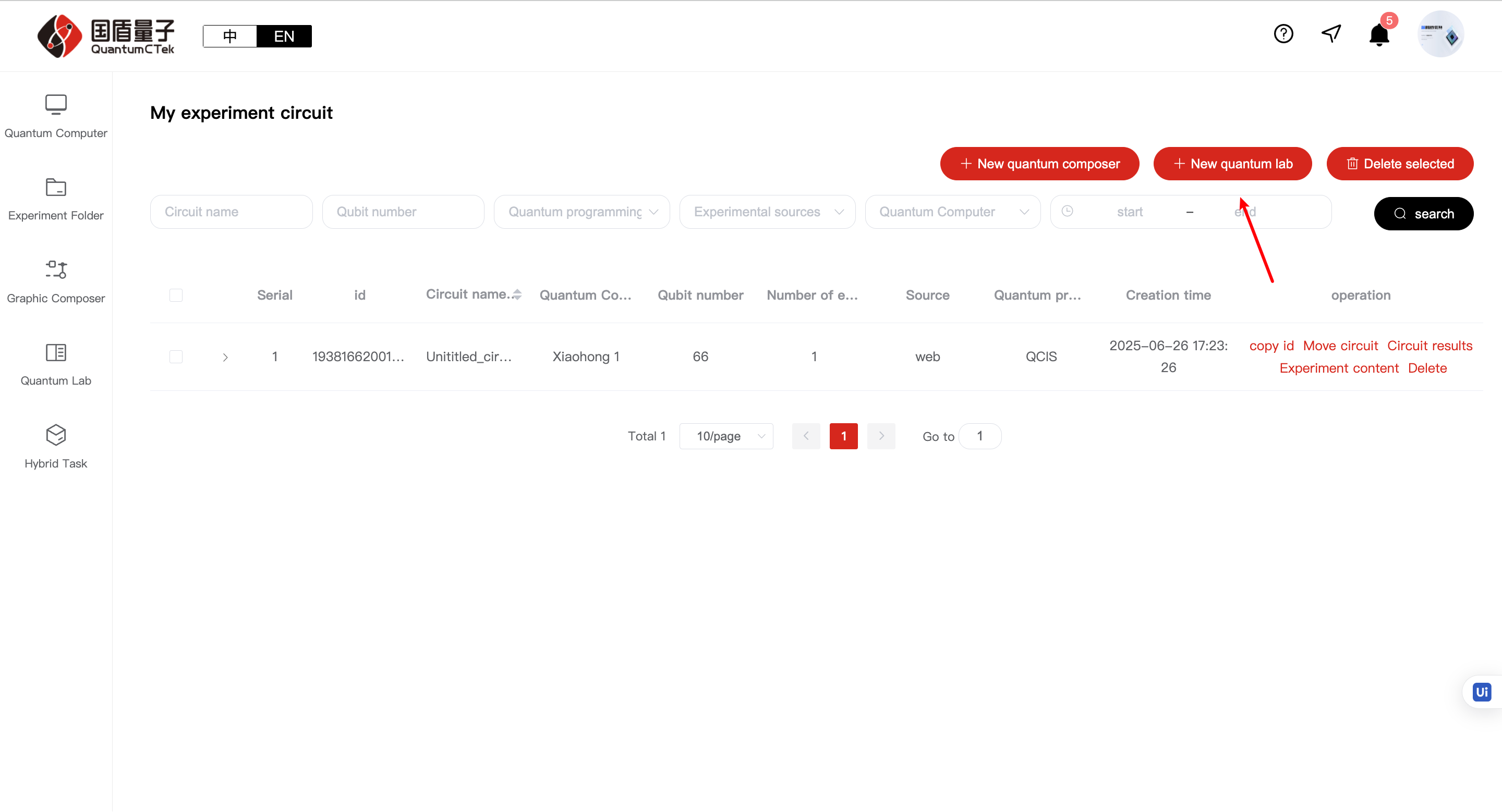
2. After entering the laboratory, click "My Experiment Collections", click "Create New Collection" to create your needed folder. After entering the folder, click "New Graphical Experiment" or "New Programming Experiment" to save circuits in that folder
5.4 Programming Laboratory
For more complex quantum circuits or those with other calling requirements, using only graphical mode or code writing in graphical mode is insufficient. Therefore, we provide SDK calling mode and a Python programming environment for SDK calls on the website
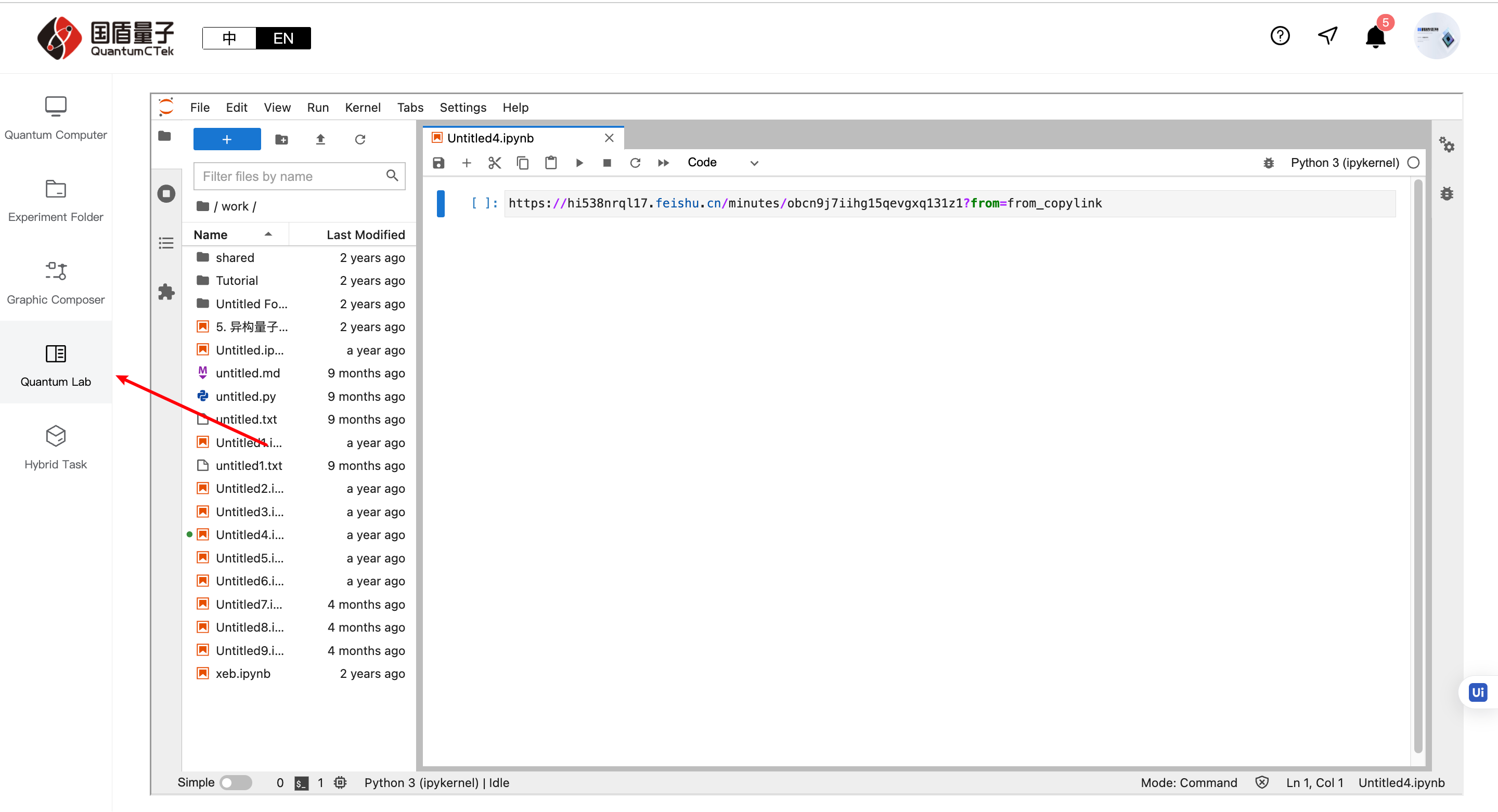
5.4.1 Enter Programming Laboratory
There are three paths to write a quantum circuit:
Method 1:
Method 2:
Method 3:
1) Programming Laboratory uses Jupyter Hub environment, can use Python-wrapped quantum computing instructions or compilation language. For offline experiments, you need to install the runtime environment. Since QuantumCTek Computing Cloud Platform has pre-installed all environments, you can run experiment code directly
2) For detailed programming tutorials and compilation language usage, please refer to the "Tutorial" file in the programming environment
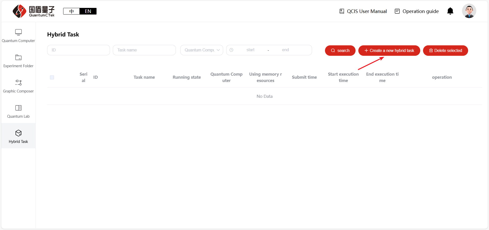
5.5. Hybrid Tasks
Hybrid tasks, also known as “Quantum-Classical Fusion,” represent a new hybrid computing architecture that integrates quantum computing with classical computing. It leverages the powerful parallel processing capabilities of quantum computers together with the efficient numerical computation capabilities of supercomputers. In this way, tasks suitable for quantum computing benefit from quantum acceleration, while other tasks are handled by the supercomputer.
5.5.1 Running Hybrid Tasks
Currently, hybrid tasks can only be executed by uploading files. On the Hybrid Tasks page, click create a new hybrid task.
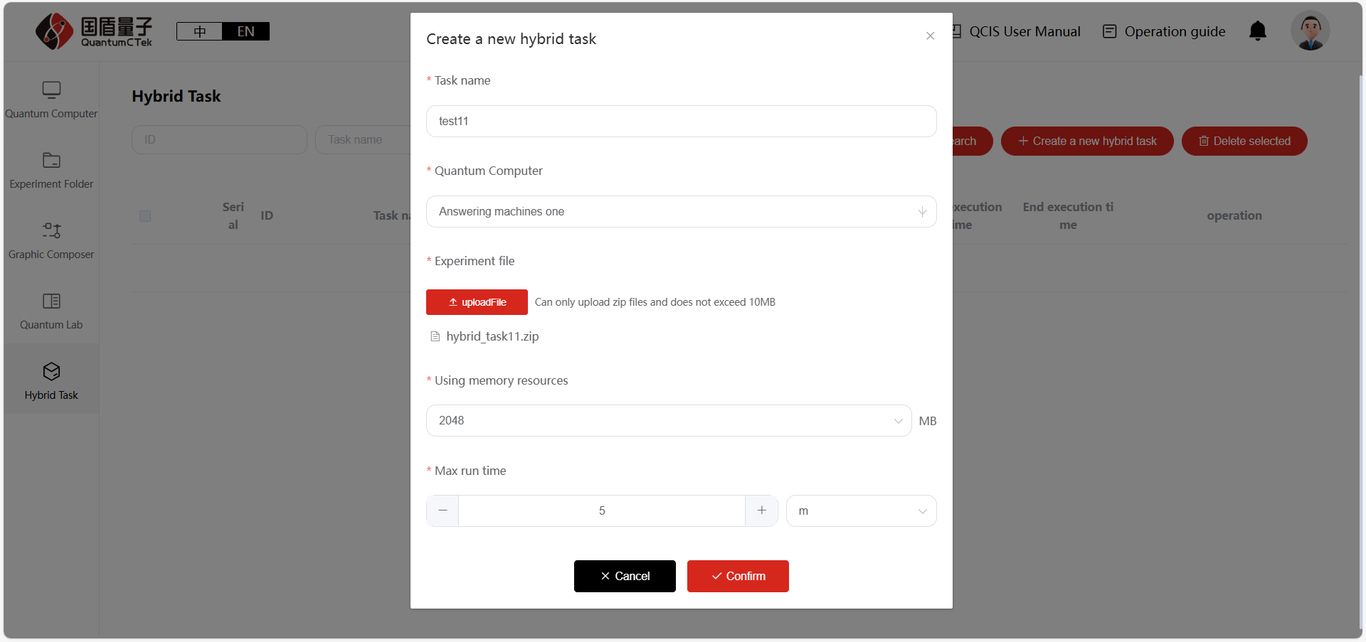
In the pop-up window, upload the code files to be executed, fill in the task parameters, and click Confirm to submit the task.
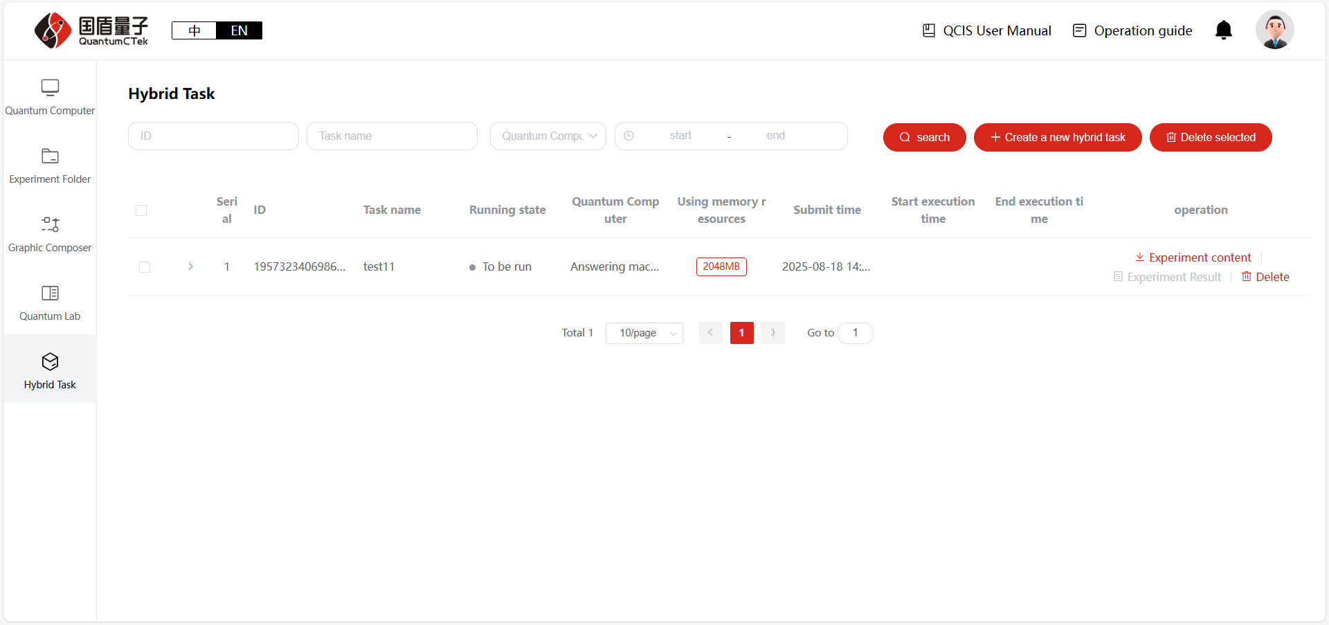
After the experiment is completed, you can download the results. The management of hybrid tasks is similar to the Experiment Folder page, supporting operations such as search, download, and delete.
Appendix. Related Learning Materials
1) QuantumCTek Computing Cloud Platform Teaching Video Series: https://quantumctek-cloud.com/course/1594586161685209182.html
2) Programming Laboratory and Quantum Program Writing Tutorial: https://quantumctek-cloud.com/codeLab.html
3) Quingo Official Learning Site: https://gitee.com/quingo
4) isQ Official Tutorial: http://www.arclightquantum.com/isq-core/index.html